
Digital camera lens

A digital camera and lens technology, applied in optics, instruments, optical components, etc., can solve the problems of not considering the processing error of plastic lenses, the high precision requirements of aspheric lenses, and the degradation of imaging quality, so as to achieve easy mass production , the number of lenses is small, the effect of easy production

Inactive Publication Date: 2009-06-24
NINGBO GUANGBO DIGITAL TECH
View PDF8 Cites 1 Cited by
  • Summary
  • Abstract
  • Description
  • Claims
  • Application Information

AI Technical Summary

Problems solved by technology

At present, Japan, Taiwan and other digital camera lenses use a large number of aspheric lens technology, because their aspheric mold processing and injection molding technology are relatively mature, but in mainland China, because the aspheric lens processing technology is not very mature, and Generally, digital camera lenses have high requirements on the accuracy of aspheric lenses. Therefore, under the current technical level in China, it is possible to design and manufacture digital camera lenses that take advantage of the advantages of aspheric surfaces and can be mass-produced. problem to be solved
For example, there are processing errors in the manufacturing process of plastic lenses, and if they are directly used to assemble the lens, it will inevitably cause a decline in imaging quality and cannot be used, so further improvement is needed
[0004] The Chinese patent "digital camera lens" whose patent number is 200410026704.2 has a very good improved design, but because the number of lenses is only three, the number of images caused by the lens is only about 1.3 million, which cannot satisfy the requirements at all. The needs of current digital cameras have not taken into account the processing error caused by the use of plastic lenses, so there are inevitably similar technical problems as above

Method used


Image

  • Digital camera lens
  • Digital camera lens
  • Digital camera lens

Examples


Embodiment Construction

[0054] The present invention will be further described in detail below in conjunction with the accompanying drawings and embodiments.

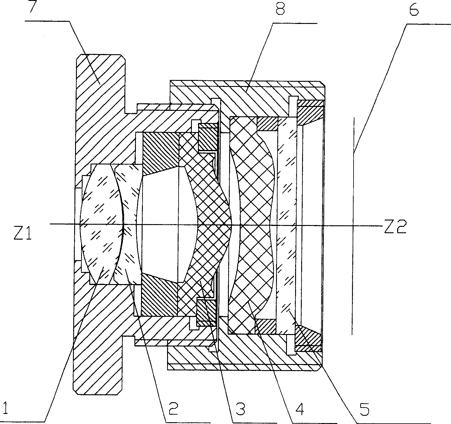
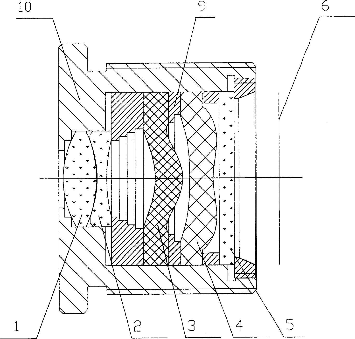
[0055] see reference figure 1 , the digital camera lens of the present invention comprises the first lens 1, the second lens 2, the third lens 3, the fourth lens 4, and the plate glass 5 sequentially from the object side, wherein Z1 represents the object side, Z2 represents the image side, and the digital camera lens It also includes a diaphragm before the surface of the first lens 1, which functions to limit the total amount of light entering the lens, and also has a plate glass 5 on the side of the fourth lens near the image side, which acts to coat a layer of light on its surface. The infrared cut-off filter is used to cut off all infrared rays whose glass length is more than 645mm. Of course, the infrared cut-off filter can also be coated on the surface of the first lens; a cmos image is arranged on the side of the flat glass 5 near the im...


PUM

PropertyMeasurementUnit
dispersion coefficientaaaaaaaaaa
refractive indexaaaaaaaaaa
dispersion coefficientaaaaaaaaaa

Abstract

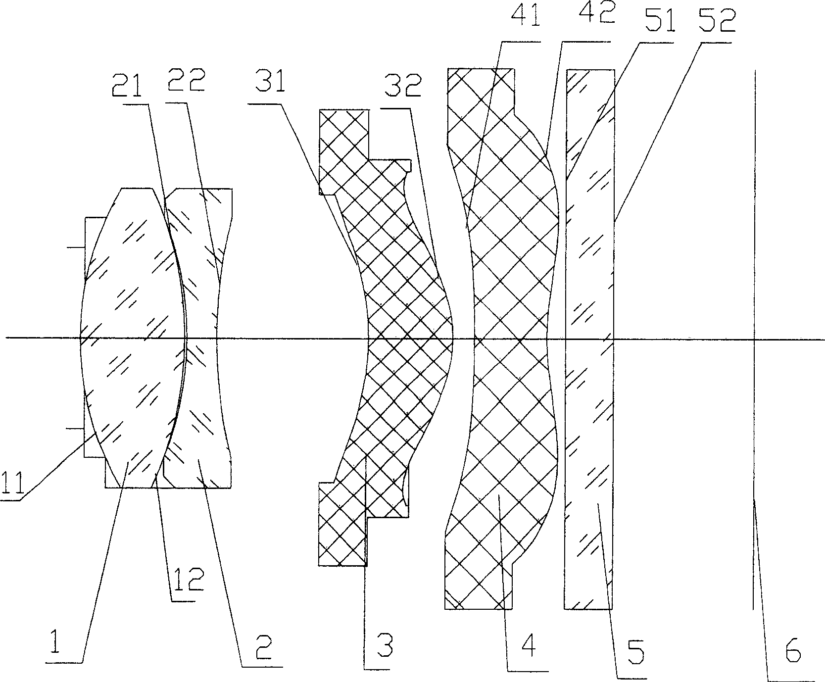
The invention relates to a digital camera lens, which sequentially includes from the object side to the image side: the first lens is a biconvex spherical lens, which is made of glass; the second lens is a biconcave lens, and the material is glass; the third lens is a crescent lens , including double aspheric surfaces, the material is PMMA; the fourth lens is a crescent-shaped double aspheric surface, the material is PMMA, and there is a fine-tuning structure between the third lens and the fourth lens to adjust their horizontal spacing. The digital camera lens of the present invention adopts a 2G2P structure, wherein 2P is a plastic double-sided aspheric surface, and 2G is a glass spherical surface, so it can effectively correct various optical aberrations and achieve high pixel requirements of the lens. The adjustment can effectively eliminate the errors caused by the aspherical production process, greatly reduce the requirements for the aspherical injection molding process, and successfully realize mass production under the current technical production conditions in China.

Description

technical field [0001] The invention relates to a digital camera lens, in particular to a fixed-focus digital camera lens matched with a high-pixel image sensor. Background technique [0002] With the development of multimedia imaging technology, digital cameras and video cameras are more and more favored by consumers. People pursue miniaturization, clear imaging and cheap prices for digital cameras. Therefore, it is necessary to design and manufacture lenses that can meet the above requirements . [0003] Under the current technical conditions, aspheric lenses are usually used to obtain digital camera lenses that can meet the above requirements, because aspheric lenses can partially reduce the aberrations caused by spherical lenses in the lens, and at the same time reduce the lens volume, and at the same time achieve Better optical performance. At present, Japan, Taiwan and other digital camera lenses use a large number of aspheric lens technology, because their aspheric ...

Claims


Application Information

Patent Timeline
Patent Type & Authority Patents(China)
IPC IPC(8): G02B9/34G02B13/18G02B1/04
Inventor 王利平丁洪兴陈燕杨士力
Owner NINGBO GUANGBO DIGITAL TECH
Learn More