Electromagnetic impulse valve service lifetime rapid test device and test method thereof

A technology of electromagnetic pulse valve and testing device, which is applied in the direction of measuring device, testing of machine/structural components, instruments, etc., can solve the problems of increasing economic and energy consumption burden, huge testing device, long testing period, etc., and achieves rapid testing. , The effect of stable air pressure and low noise

Active Publication Date: 2009-07-08
SHANGHAI SHANGTAI ENVIRONMENTAL COMPONENTS
View PDF4 Cites 0 Cited by
  • Summary
  • Abstract
  • Description
  • Claims
  • Application Information

AI Technical Summary

Problems solved by technology

[0002] In order to improve the performance and quality of the electromagnetic pulse valve, it is often necessary to test the service life of the electromagnetic pulse valve, such as figure 1 As shown, it is a schematic diagram of the structure of the original rapid test device for the service life of the electromagnetic pulse valve. Box 6 and silencer box 7, the entire electromagnetic pulse valve, namely electromagnetic head 1, valve cover 2, diaphragm 3, and valve body 4, are installed on the air distribution box (air bag) 6, and the output end of the valve is emptied or connected to the blowing pipe 5. Connect and insert the blowing pipe 5 into the silencer box 7. After connecting the control power supply, the electromagnetic pulse valve will blow continuously and repeatedly. Due to the size of the electromagnetic pulse valve, the blowing volume varies from tens to hundreds of liters each time. After blowing, the air pressure of the air distribution box (air bag) drops, and it takes about 10 seconds to replenish the gas until the air pressure recovers. It takes 3-4 months to operate 1 million times. If the gas replenishment is accelerated, the gas source needs to be increased. Equipment capacity, long test cycle, high energy consumption, high noise, and large test equipment will increase the burden on economy and energy consumption

Method used


Image

  • Electromagnetic impulse valve service lifetime rapid test device and test method thereof
  • Electromagnetic impulse valve service lifetime rapid test device and test method thereof
  • Electromagnetic impulse valve service lifetime rapid test device and test method thereof

Examples


Embodiment

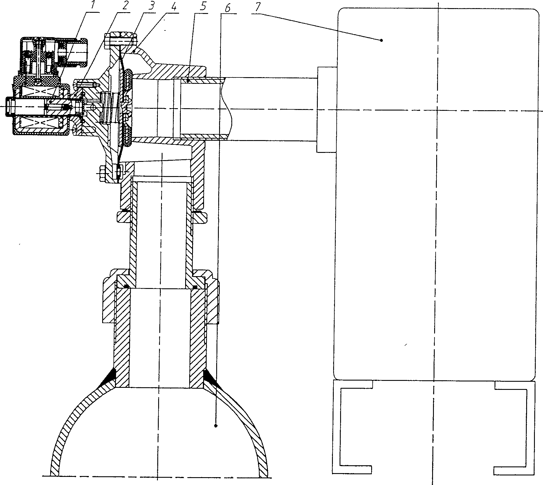
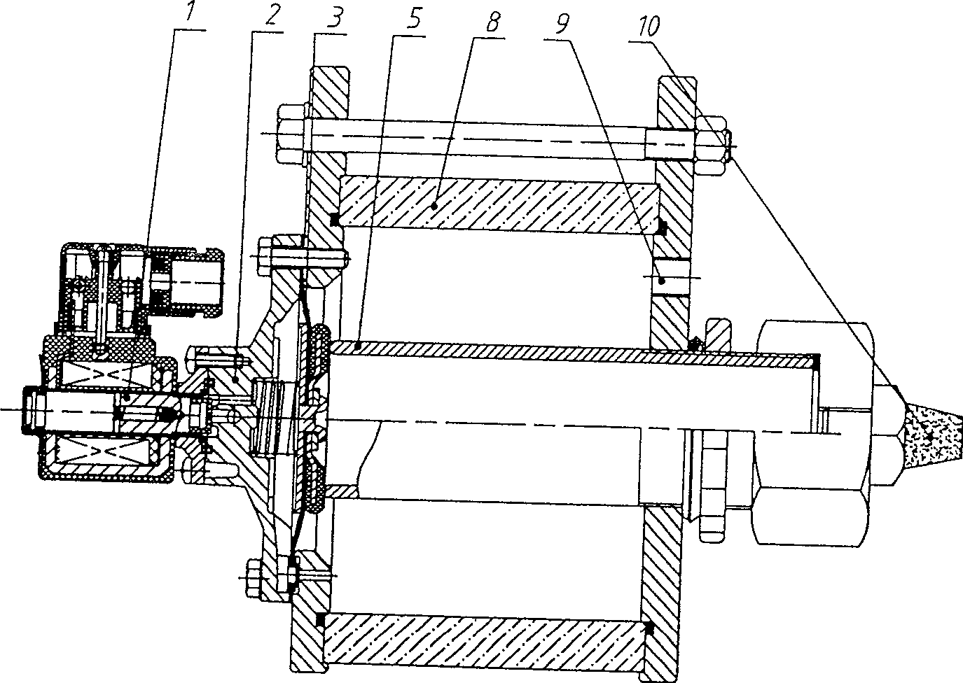
[0019] Such as figure 2 As shown, it is a schematic structural diagram of a quick test device for the service life of an electromagnetic pulse valve. The quick test device for a service life of an electromagnetic pulse valve consists of a solenoid head 1, a valve cover 2, a diaphragm 3, a blowing pipe 5, and a transparent box 8 And muffler mouth 10 forms.

[0020] The solenoid head 1 is connected with the valve cover 2, the valve cover 2 is connected with the transparent box end cover A12, the diaphragm 3 is fixed between the valve cover 2 and the transparent box end cover A12, and is in contact with one end of the blowing pipe 5, and the blowing pipe 5 passes through The other end of the transparent case 8 is closed or connected with the muffler nozzle 10 through a nut.

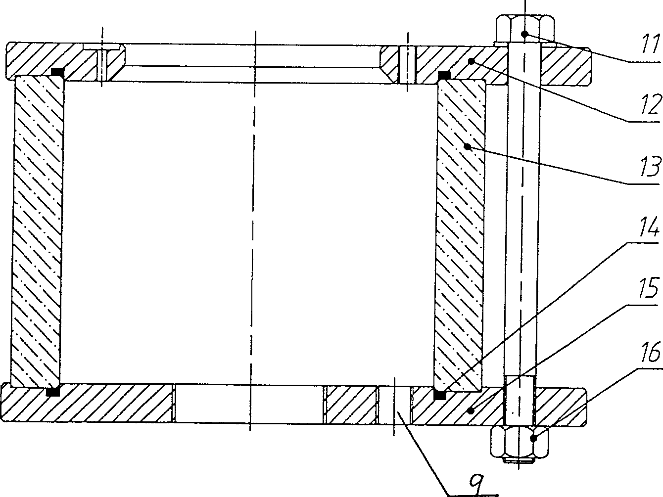
[0021] Described transparent box 8 is made up of air inlet 9, hexagonal bolt 11, end cover A12, plexiglass tube 13, seal ring 14, end cover B15, hexagonal nut 16, and organic glass tube 13 two sides are ma...


PUM


Abstract

The invention relates to a quick test device for the service life of an electromagnetic pulse valve. It is located between the valve cover and the end cover A of the transparent box, and is in contact with one end of the blowing pipe. The blowing pipe passes through the other end of the transparent box to close or connect to the muffler nozzle through a nut. Its test method is characterized in that the method is as follows: connect the air source from the air inlet, connect the control power supply; start the electromagnetic pulse valve, the electromagnetic head of the electromagnetic pulse valve moves to make the diaphragm move back and forth, the electromagnetic head and the diaphragm Each action does not cause the air pressure to drop, and the action frequency can reach once every 1-2 seconds. Continuously test until the electromagnetic pulse valve is damaged, and record the number of electromagnetic pulse valve actions. The invention has the advantages of quick test, low energy consumption, low noise, and the small volume of the test device facilitates the test under high and low temperature conditions.

Description

technical field [0001] The invention relates to a quick test device for the service life of an electromagnetic pulse valve and a test method thereof, which are used for testing the service life of an electromagnetic pulse valve and belong to the technical field of test devices. Background technique [0002] In order to improve the performance and quality of the electromagnetic pulse valve, it is often necessary to test the service life of the electromagnetic pulse valve, such as figure 1 As shown, it is a schematic diagram of the structure of the original rapid test device for the service life of the electromagnetic pulse valve. Box 6 and silencer box 7, the entire electromagnetic pulse valve, namely electromagnetic head 1, valve cover 2, diaphragm 3, and valve body 4, are installed on the air distribution box (air bag) 6, and the output end of the valve is emptied or connected to the blowing pipe 5. Connect and insert the blowing pipe 5 into the silencer box 7. After conne...

Claims


Application Information

Patent Timeline
Patent Type & Authority Patents(China)
IPC IPC(8): G01M19/00G01M99/00
Inventor 朱德生
Owner SHANGHAI SHANGTAI ENVIRONMENTAL COMPONENTS
Why Eureka
Try Eureka