Special pressure for industrial detonating cap and method for compressing detonating cap explosive

A press and detonator technology, applied in the field of press manufacturing, can solve the problems that are not conducive to the use of automatic detonator filling lines, large basic investment in hydraulic pump stations, and large volume of hydraulic presses, etc., to achieve convenient automatic control, low equipment cost, and basic investment Reduced effect

Inactive Publication Date: 2009-07-15
杭州强立机械有限公司
View PDF8 Cites 0 Cited by
  • Summary
  • Abstract
  • Description
  • Claims
  • Application Information

AI Technical Summary

Problems solved by technology

[0002] Most of the domestic existing detonator and explosive filling presses use 63-ton hydraulic presses. Under the existing production technology, the maximum pressure of the industrial detonator and explosive pressing process does not exceed 30 tons, and more than 50% of the energy is wasted.
The 63-ton hydraulic press is large in size, and the basic investment of the hydraulic pump station is large, which is not conducive to the use in the detonator automatic filling line

Method used


Image

  • Special pressure for industrial detonating cap and method for compressing detonating cap explosive

Examples


Embodiment 1

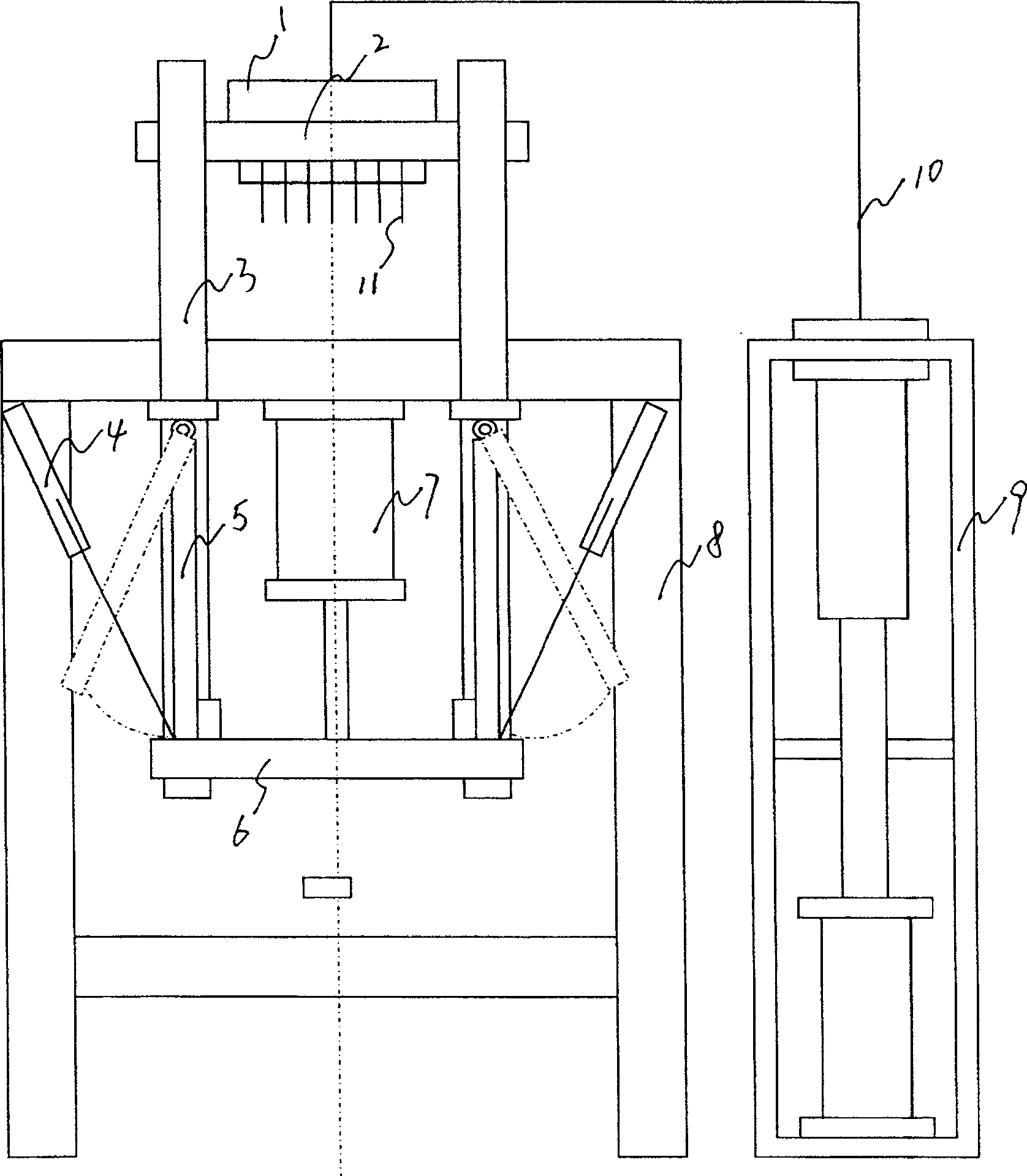
[0009] Example 1: Refer to the attached figure 1 . Special press for industrial detonators, which includes frame 8 and reference attached figure 1 Processed and manufactured according to existing technology. The four uprights 3 refer to the uprights with column sleeves. The four uprights 3 are respectively located (installed on) the side of the frame 8 and the lower ends of the four uprights are connected to the lifting plate 6, and the upper part of the four uprights is connected to the hydraulic compensation head 2. , The hydraulic compensation head 2 is composed of a hydraulic compensator 1 and a plurality of hydraulic plungers 11, and the plurality of hydraulic plungers 11 are respectively located in the hydraulic lifting cavity of the hydraulic compensator 1 and extend together in the state of hydraulic pressure. Retract with the hydraulic pressure unloaded. The pressurization (loading) or unloading of the hydraulic compensation head 2 depends on the gas-liquid pressurization...

Embodiment 2

[0010] Example 2: On the basis of Example 1, the method of compressing detonator explosives by a special industrial detonator press. After the turnover die with a fire detonator is sent to the positioning seat of the turnover die of the industrial detonator press, the piston in the main cylinder pushes The lifting plate moves down, and the multiple plungers in the hydraulic compensation head descend from the top dead center to the inner surface of the tube shell. The self-locking rod in the self-locking mechanism is pushed to the vertical state by the cylinder and the four-column lifting mechanism is locked. The gas-liquid pressurization mechanism pressurizes the hydraulic compensation head and directly acts on the multiple plungers in the hydraulic compensation head. The plunger completes the compression of the explosive loaded in the detonator. When the compression reaches the set value, The gas-liquid pressurizing mechanism is unloaded, the self-locking mechanism unlocks the fo...


PUM


Abstract

The invention relates to a special press machine for industrial detonators, which includes a frame, four columns are respectively located on the side of the frame and the lower ends of the four columns are connected with the lifting plate, and the upper parts of the four columns are connected with the hydraulic compensation machine head, the hydraulic compensation machine The head hydraulic cavity communicates with the hydraulic port of the gas-liquid booster mechanism through the oil pipe, the base of the main cylinder is fixed on the back of the worktable of the frame and the end of the piston rod of the main cylinder is connected with the lifting plate. Advantages: First, the equipment cost is low, the volume is reduced, and the basic investment is reduced; second, the characteristics of detonator pressure are fully utilized, the energy consumption of the equipment is reduced, and the noise is eliminated; the third is convenient automatic control, which is beneficial to the detonator automatic filling line technological progress.

Description

Technical field: [0001] The invention relates to a special press for industrial detonators and a method for compressing explosives for detonators, and belongs to the field of press manufacturing. Background technique: [0002] Most of the existing domestic detonator explosive filling presses are 63-ton hydraulic presses. Under the existing production technology, the maximum pressure of the industrial detonator explosive filling process does not exceed 30 tons, and more than 50% of the energy is wasted. The large size of the 63-ton hydraulic press, coupled with the large investment in the hydraulic pump station, is not conducive to use in the detonator automatic filling line. Summary of the invention: [0003] Design purpose: to avoid the deficiencies in the background technology, to design a special press for industrial detonators and a method for compressing detonator explosives that is small in size, low in energy consumption, and is beneficial to the use of detonator automate...

Claims


Application Information

Patent Timeline
Patent Type & Authority Patents(China)
IPC IPC(8): F42C19/08
Inventor 钟秉松张海伟
Owner 杭州强立机械有限公司
Why Eureka
Try Eureka