Optical fiber pipe hydraulic sensor

A hydraulic sensor and pipeline technology, which is applied in the direction of using optical devices to transmit sensing components, instruments, and fluid pressure measurement using optical methods, and can solve problems such as inability to measure pipeline hydraulic pressure, sensitivity to temperature changes, and uneven force on optical fibers. , to achieve the effect of easy guarantee of process consistency, good repeatability, and avoid direct bonding

Inactive Publication Date: 2009-07-15
INST OF SEMICONDUCTORS - CHINESE ACAD OF SCI
View PDF4 Cites 0 Cited by
  • Summary
  • Abstract
  • Description
  • Claims
  • Application Information

AI Technical Summary

Problems solved by technology

The optical fiber pressure sensor produced in this way is greatly affected by the packaging process; the uneven glue layer will cause uneven force on the optical fiber, which is prone to chirp; the hydraulic pressure of the pipeline cannot be measured, and it is more sensitive to temperature changes

Method used


Image

  • Optical fiber pipe hydraulic sensor

Examples


Embodiment Construction

[0026] In order to make the object, technical solution and advantages of the present invention clearer, the present invention will be described in further detail below in conjunction with specific embodiments and with reference to the accompanying drawings.

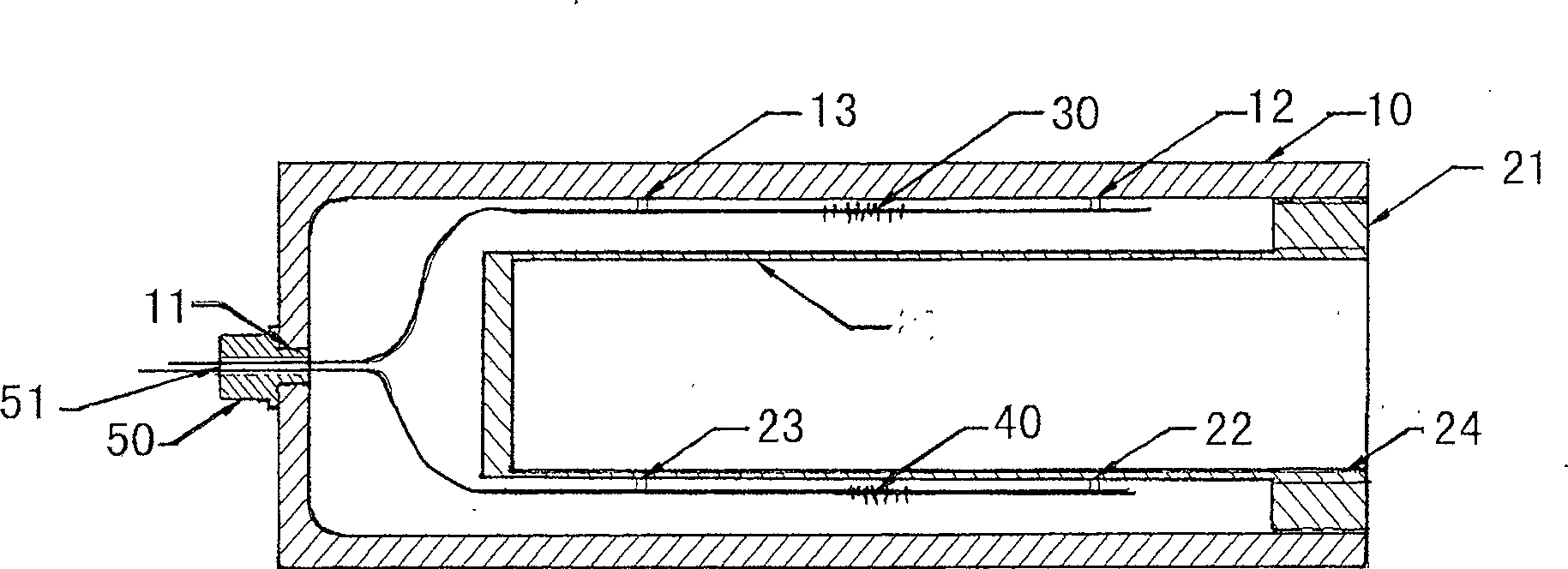
[0027] like figure 1 as shown, figure 1 It is a schematic cross-sectional view of the structure of the optical fiber pipeline hydraulic sensor provided by the present invention. The fiber optic pipeline hydraulic sensor includes:

[0028] A support cylinder 10, the support cylinder 10 has a cylindrical structure, and a circular hole 11 is formed in the lower part thereof, and the inner wall of the support cylinder 10 is bonded with two bosses 12, 13 along the axial direction for installing the fiber grating 30;

[0029] An inner cylinder 20, the inner cylinder 20 is installed inside the support cylinder 10, the opening end of the inner cylinder 20 has a flange 21, the outer diameter of the flange 21 is the same as the i...


PUM


Abstract

The invention provides a fiber duct hydraulic pressure transducer, which is characterized in that the invention comprises a support tube in the cylindric structure; an inner core arranged inside the support tube; a first fiber Bragg grating; a second fiber Bragg grating. The lower part of the support tube is provided with a round orifice; two lug bosses are bonded on the inner wall of the support tube in the axial direction, and are used to install the fiber Bragg gratings. The open end of the inner core is provided with a flange; the outside diameter of the flange is the same with the inside diameter of the support tube; two lug bosses are bonded on the external wall of the inner core in the axial direction, and are used to install the fiber Bragg gratings. Both ends of the first fiber Bragg grating are bonded on the two lug bosses on the inner wall of the support tube. Both ends of the second fiber Bragg grating are bonded on the two lug bosses on the external wall of the inner core. The fiber tips of the two fiber Bragg gratings are led out from the round orifice of the lower part of the support tube and are connected with a checkout equipment.

Description

technical field [0001] The invention relates to the technical field of optical fiber sensors, in particular to an optical fiber pipeline hydraulic sensor. Background technique [0002] Compared with the corresponding conventional sensors, optical fiber sensors have obvious advantages in terms of sensitivity, dynamic range, reliability, etc., especially in the fields of construction, petroleum, and military applications. [0003] The optical fiber pressure sensor is an instrument that detects the pressure of the surrounding environment by using the light transmission characteristics of the optical fiber and various modulation effects generated by its interaction with the surrounding environment. Compared with traditional pressure sensors, it has the following main advantages: high pressure sensitivity, no electromagnetic interference, light weight, high temperature resistance, compact structure, high reliability, and the advantages of both information sensing and optical info...

Claims


Application Information

Patent Timeline
Patent Type & Authority Patents(China)
IPC IPC(8): G01L11/02G01L19/04G01D5/353G02B6/34
Inventor 张文涛李芳刘育梁
Owner INST OF SEMICONDUCTORS - CHINESE ACAD OF SCI
Why Eureka
Try Eureka