
Permanent magnetism electromagnetic blending magnet design method of electromagnetic type maglev train and structure

A maglev train and electromagnetic hybrid technology, applied in electric vehicles, electric traction, vehicle components, etc., can solve the problems of insufficient carrying capacity of the device, unable to meet the requirements of engineering applications, etc., to reduce the maximum ampere-turn, the adjustment range is large, the The effect of the requirement of orbital accuracy

Inactive Publication Date: 2009-07-29
NAT UNIV OF DEFENSE TECH
View PDF3 Cites 0 Cited by
  • Summary
  • Abstract
  • Description
  • Claims
  • Application Information

AI Technical Summary

Problems solved by technology

M3 in the United States has carried out in-depth research in this field, but due to the limitation of the installation position of the permanent magnet, the carrying capacity of the device is insufficient, and it cannot meet the requirements of engineering applications.

Method used


Image

  • Permanent magnetism electromagnetic blending magnet design method of electromagnetic type maglev train and structure
  • Permanent magnetism electromagnetic blending magnet design method of electromagnetic type maglev train and structure
  • Permanent magnetism electromagnetic blending magnet design method of electromagnetic type maglev train and structure

Examples


Embodiment Construction

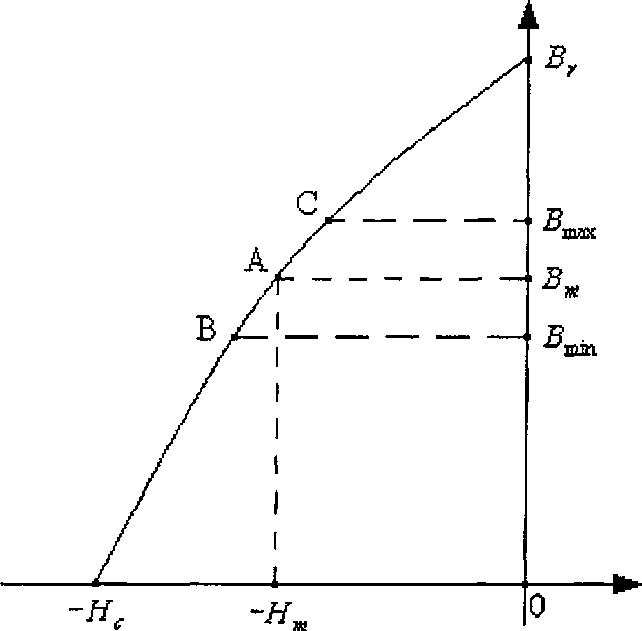
[0024] In the field of permanent magnet research, the key to designing permanent electromagnetic hybrid magnets is to select the working point of the permanent magnet reasonably. As we all know, the B-H curve of a permanent magnet is determined by the material, which reflects the changing trend and range of the working point of the permanent magnet. Such as figure 1 shown, where B m is the magnetic density at the working point, H m is the magnetic field strength at the working point, B r is the residual magnetism of the permanent magnet, H c is the coercive force of the permanent magnet. If the working point of the permanent magnet is too high or too low, its variation range will be very small, which directly leads to a very limited variation range of the levitation force provided by the hybrid magnet, making the dynamic adjustment process of the maglev train more difficult, or even unable to achieve stability suspended.

[0025] According to the magnetic flux continuity...


PUM


Abstract

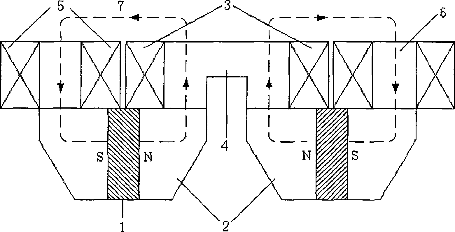
The invention relates to a method for designing a hybrid magnet of a permanent magnet and an electromagnet of an electronic-magnetic maglev. By adjusting a working point of the permanent magnet according to a changing range of bearing weight of the maglev, the working point of the permanent magnet is near a point of the maximum energy when the changing range of bearing weight is relatively wide. The invention also provides a structure of the hybrid magnet of the permanent magnet and the electromagnet of the electronic-magnetic maglev, which comprises the permanent magnet, an electromagnetic coil, an iron core and a magnetic yoke. The electromagnetic coil is winded on the iron core by using electricity conducting material and forms a magnetic pole with the iron core. The electromagnetic pole is arrayed in a row. The magnetic yoke is arranged on the external side of an S pole and an N pole of the permanent magnet; the permanent magnet is tightly clamped from both sides and is in joint with the bottom of the magnetic pole of the electromagnet. The magnetic yoke and the permanent magnet are arranged between two nearby magnetic poles of the electromagnet. The method of the invention can select the working point of the permanent magnet according to requirements on bearing capability. The designed hybrid magnet can meet different requirements on bearing capability.

Description

【Technical field】 [0001] The invention relates to a maglev train, in particular to a design method for a permanent electromagnetic hybrid magnet of an EMS type (electromagnetic type) maglev train. 【Background technique】 [0002] The working mechanism of the EMS type maglev train is to use magnets to attract the rails to provide levitation force, and by changing the levitation force provided by the magnets, the train can maintain a stable levitation. Therefore, the levitation magnet is a key component of the maglev train, which determines the load capacity of the maglev train. capacity and suspension performance. [0003] The levitation magnets of EMS type maglev trains usually adopt electromagnets, for example, TR in Germany and HSST in Japan all use electromagnets. In order to improve the carrying capacity, it is usually required to select a larger current of the electromagnet and a smaller levitation gap, which often leads to a large volume and capacity of the on-board po...

Claims


Application Information

Patent Timeline
Patent Type & Authority Patents(China)
IPC IPC(8): B60L13/04
Inventor 李云钢程虎陈革陈贵荣陈慧星吴志添张鼎
Owner NAT UNIV OF DEFENSE TECH
Learn More