Heat exchanger for heat pump

A technology of heat exchangers and heat pumps, applied in the direction of indirect heat exchangers, heat exchanger types, heat exchange equipment, etc., can solve the problems of unavailable evaporators, increased air flow resistance, and increased heat transfer resistance, etc., to achieve Disturb the temperature boundary layer, enhance the mixing of airflow, and enhance the effect of heat transfer

Active Publication Date: 2009-08-05
GREE ELECTRIC APPLIANCES INC
View PDF6 Cites 2 Cited by
  • Summary
  • Abstract
  • Description
  • Claims
  • Application Information

AI Technical Summary

Problems solved by technology

When this kind of heat exchanger is operated under refrigeration conditions, the condensed water precipitated on the surface of the evaporator will adhere to the surface of the evaporator and accumulate in the channel, which will greatly increase the heat transfer resistance and affect the heat transfer efficiency of the evaporator
At the same time, because the condensed water cannot be discharged in time, it will block the air flow channel, increase the flow resistance of the air, and further affect the heat exchange efficiency of the evaporator. In serious cases, the condensed water may be blown into the room, resulting in the unusable evaporator.
[0004] To sum up, the traditional parallel flow heat exchanger has the same problem when it is used as a condenser and an evaporator: condensed water or defrosted water is easy to adhere to the fins to block the air duct and increase the wind resistance; The outer surface of the tube is attached, and the thermal resistance caused by the attachment on the surface of the tube is greater than the thermal resistance caused by the attachment to the heat sink, so the heat exchange efficiency of the heat exchanger is seriously reduced
[0005] U.S. Patent No. 6,964,296B2 discloses an outdoor heat exchanger for heat pumps, which is dedicated to solving the problem of condensed water removal. The disclosed heat exchanger has a serious problem: due to the strong wind force inside the heat exchanger, condensed water droplets are easy to be directly Blows out of the heat exchanger instead of downwards under the force of gravity
The applicant of this case provided a new type of heat pump heat exchanger that can remove condensed water in China Patent Application No. 200620067330.3, but the technology disclosed in this application is difficult to realize in terms of processing technology
[0006] In addition, while considering the problem of condensed water removal in the above-mentioned prior art, it ignores the specific improvement on the sheet type, so as to further enhance the heat exchange effect and achieve the goal of high efficiency and energy saving.

Method used


Image

  • Heat exchanger for heat pump
  • Heat exchanger for heat pump
  • Heat exchanger for heat pump

Examples


Embodiment 1

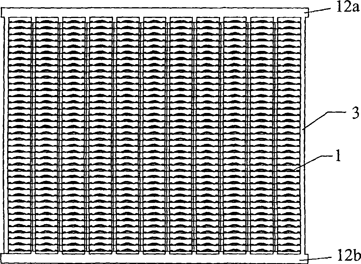
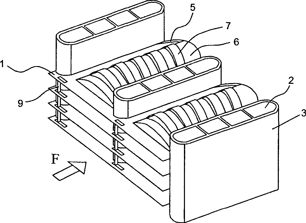
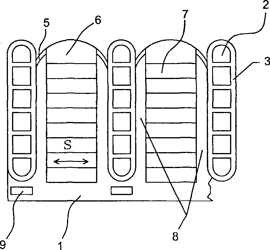
[0032] Please refer to figure 2 , image 3 , Figure 4 , Figure 5 , Figure 6 and Figure 7 , in the first embodiment, each unit heat sink includes a number of interlaced and protruding arched bridges 7, each side of the arched bridges is provided with a flow guide 8, and the flow guide 8 is connected to the end of each bridge, The condensed water or defrosting water formed above the arched bridge can flow along the surface of the bridge to both sides under the action of surface tension, and aggregate at the guide fins on both sides of the unit heat sink. The front edge of the deflector 8 is provided with a water-blocking emboss 5, and the front end of the deflector 8 is also provided with a drain 6 for discharging condensed water or defrosting water downwards. The drain 6 is arranged obliquely near the resistance An opening of the water embossment 5 . Such as Figure 4 , 5 , 6, the drain sheet 6 is a downwardly inclined concave sheet with arc-shaped edges. The unit...

Embodiment 2

[0041] Such as Figure 8 As shown, the difference between this embodiment and Embodiment 1 is that in this embodiment, the arched bridges of the unit cooling fins consist of multiple sets of two upwardly interlaced arched bridges 7a and 7b.

Embodiment 3

[0043] Such as Figure 9 , Figure 10 As shown, the difference between this embodiment and Embodiment 1 is that in this embodiment, the front ends of the two guide fins 8 of each unit heat sink are connected into one body through a flat sheet, and the water-blocking embossed lines 5 are arranged on the flat sheet and the two fins. At the front edge of the guide vane 8 , the drain vane 6 is obliquely arranged near an opening of the water blocking rib 5 . The condensed water above the arched bridge plate 7 flows to the guide plate 8 under the action of surface tension and gravity, and cannot fly out of the heat exchanger when encountering the water blocking ribs 5, but is drained downward by the drain plate 6.


PUM


Abstract

The heat pump heat exchanger disclosed by the present invention comprises headers arranged horizontally, flat tubes vertically arranged between the headers and communicated with the headers, and fins inserted horizontally between the headers. The fins include a plurality of unit cooling fins, and each unit cooling fin is located between the flat tubes. Each unit cooling fin includes a number of interlaced and protruding arched bridges, and two bridges arranged on both sides of the arched bridges and connected to the ends of each bridge. The deflector, the water-blocking embossment arranged at the front edge of the deflector, and the drainage mechanism arranged at the front end of the deflector for discharging condensed water or defrosting water downward. The invention can timely remove condensed water or defrosted water, thereby effectively preventing the condensed water or defrosted water from blocking the air duct and reducing wind resistance. Since condensed water or defrosted water is removed in time, the amount of frosting is reduced accordingly. In addition, the staggered and protruding arched bridges on the surface of the unit heat sink can effectively reduce wind resistance, disturb the temperature boundary layer, enhance the mixing of airflow, and enhance the heat transfer effect.

Description

technical field [0001] The invention relates to the field of air conditioning, in particular to a heat exchanger using flat tubes. Background technique [0002] Traditional parallel flow heat exchangers generally adopt a structure in which flat tubes and corrugated fins are stacked. When this type of heat exchanger is used as an air source heat pump condenser, a large amount of defrosting water after heating and defrosting tends to accumulate in the channel formed between the heat sink and the heat sink, and cannot be discharged, which seriously blocks the air flow channel and increases the air flow. At the same time, it is easy to make the frost layer thicker and thicker, and even freeze, which greatly reduces the performance of the heat pump. [0003] The flat tubes of the traditional parallel flow heat exchanger are arranged in the horizontal direction, and when used as an evaporator, there is a common problem of uneven liquid separation. Recently, some improved heat ex...

Claims


Application Information

Patent Timeline
Patent Type & Authority Patents(China)
IPC IPC(8): F28D1/053F28F1/32F25B39/00
Inventor 邢淑敏梁祥飞庄嵘
Owner GREE ELECTRIC APPLIANCES INC
Why Eureka
Try Eureka