Gas injection boiler using the emulsifying coke mortar combustion device

A technology of a combustion device and a steam injection boiler, which is applied to steam boilers, water-tube steam boilers, and combustion with various fuels, etc., can solve the problems of not reaching the melting point of emulsified coke slurry ash, ash, high manufacturing cost, and energy waste. , to achieve the effect of continuous and effective liquid slag removal, reduction of nitrogen oxides, efficient and stable combustion

Inactive Publication Date: 2009-08-19
广州迪森热能设备有限公司
View PDF7 Cites 0 Cited by
  • Summary
  • Abstract
  • Description
  • Claims
  • Application Information

AI Technical Summary

Problems solved by technology

It can be seen from the above analysis that, firstly, the backfired coal-water slurry liquid slagging combustion furnace is not suitable for the combustion of emulsified coke slurry; secondly, the combustion chamber temperature of the backfired coal water slurry liquid slagging combustion furnace is still low The ash melting point of the emulsified coke slurry ash cannot be reached, and the emulsified coke slurry ash cannot be liquefied; finally, the combustion chamber structure of the reverse combustion type coal-water slurry liquid slagging combustion furnace is complicated, and the manufacturing cost is high
[0007] In addition, in order to make the system operate continuously and normally, the slag receiving device at the lower part of the burner must be replaced in time, and the liquid slag also contains a large amount of waste heat that can be used. If the liquid slag is directly flowed into the slag receiving device, it will cause waste of energy
[0008] Finally, the steam dryness of the steam injection boiler can only be maintained at about 80% at present, and cannot reach 100%.

Method used


Image

  • Gas injection boiler using the emulsifying coke mortar combustion device
  • Gas injection boiler using the emulsifying coke mortar combustion device
  • Gas injection boiler using the emulsifying coke mortar combustion device

Examples


Embodiment 1

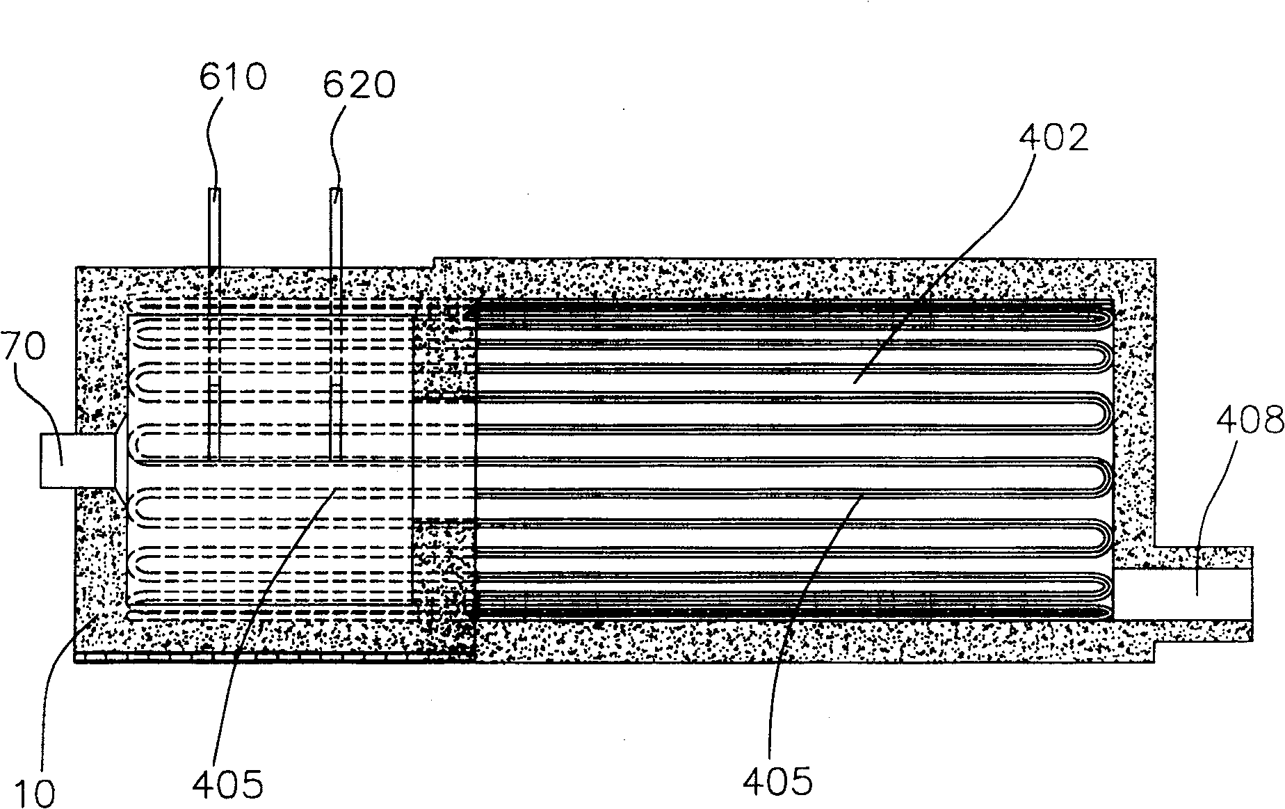
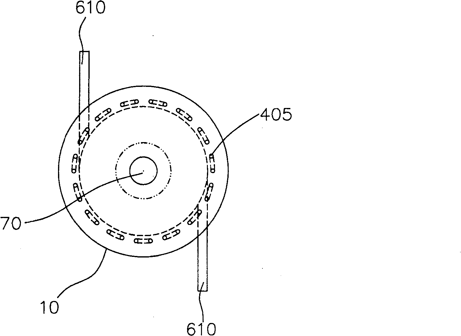
[0052] Please refer to figure 1 and figure 2 , The steam injection boiler of the present invention includes a boiler body and an emulsified coke slurry combustion device. The boiler body includes a furnace 402, a steam pipe 405 coiled in the furnace 402, and a smoke outlet 408 on one end wall of the furnace 402 away from the emulsified coke slurry combustion device. The emulsified coke slurry combustion device includes a casing 10, an emulsified coke slurry burner 70, an oil burner (not shown), and a gas burner (not shown). The emulsified coke slurry combustion device is in communication with the furnace 402.

[0053] Wherein, the steam pipe 405 extends from the furnace 402 to the side wall of the emulsified coke slurry combustion device and then folds back into the furnace 402. In this embodiment, the steam pipe 405 is folded back fifteen times in the side wall of the emulsified coke slurry combustion device. Specifically, those portions of the steam pipe 405 in the side wall a...

Embodiment 2

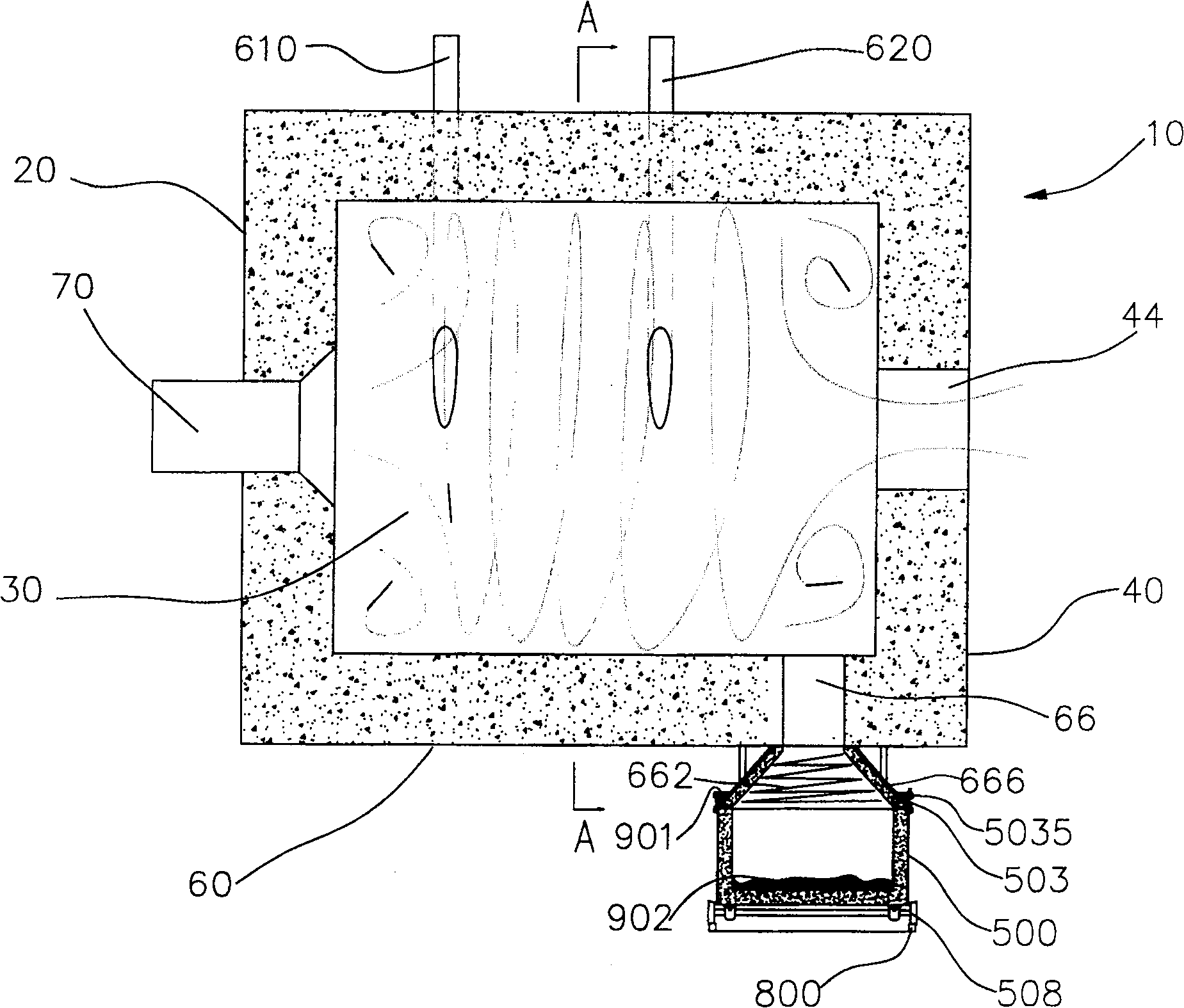
[0074] Please refer to Figure 5 and Figure 6 As another embodiment of the present invention, it is similar to Example 1, except that:

[0075] The opening area of ​​the liquid slag outlet 66 on the inner wall of the side wall 60 is approximately equal to one twentieth of the cross-sectional area of ​​the combustion space 30.

[0076] The vertical distance between the inner wall of the front end wall 20 and the inner wall of the rear end wall 40 is 1.5 times the inner diameter of the combustion space 30.

[0077] The diameter of the outlet 44 is approximately equal to one-half of the inner diameter of the combustion space 30, and a conical transition chamber 48 is formed between the outlet 44 and the side wall 60 of the casing 10. That is, a flared opening is formed in the rear end wall 40.

[0078] There are four emulsified coke slurry burners 70. The four emulsified coke slurry burners 70 are respectively installed on the front end wall 20 and are distributed at equal intervals...

Embodiment 3

[0086] As another implementation manner of the present invention, it is similar to Example 1, except that:

[0087] The boiler body includes three steam pipes 405 coiled in the furnace 402, and each steam pipe 405 is folded five times in the side wall 60 of the emulsified coke slurry combustion device.

[0088] The steam injection boiler using the emulsified coke slurry combustion device is provided with two spaced apart liquid slag outlets 66 of the same size. The opening area of ​​each liquid slag outlet 66 on the inner wall of the side wall 60 is approximately equal to the cross-sectional area of ​​the combustion space. One-thirtieth.

[0089] The two liquid slag outlets 66 are surrounded by the same transition cavity 666 and connected to the slag containing space of the same slag discharge truck 500.

[0090] The vertical distance between the inner wall of the rear end wall 40 and the inner wall of the front end wall 20 is 4 times the inner diameter of the combustion space 30....


PUM


Abstract

The invention discloses a steam injection boiler adopting an emulsified coke slurry combustion device, which comprises a boiler body and an emulsified coke slurry combustion device. The smoke outlet on one end wall of the device. The emulsified coke slurry combustion device includes a shell surrounded by a front end wall, a rear end wall, and a side wall. A cylindrical combustion space is formed inside the shell. The front end wall is provided with At least one emulsified coke burner, and at least one oil burner and / or at least one gas burner, an outlet is opened on the rear end wall, and the outlet communicates with the furnace, wherein at least a part of the steam pipe in the furnace extends to the emulsified coke slurry In the side wall of the combustion device and adjacent to the inner surface of the side wall. In the present invention, the steam pipe is extended and arranged in the side wall of the combustion device, which effectively improves the dryness of the steam to 100%.

Description

Technical field [0001] The invention relates to a steam injection boiler, in particular to a steam injection boiler using an emulsified coke slurry combustion device. Background technique [0002] The cleaner energy sources currently used by steam injection boilers are mainly oil, natural gas or coal gas, etc. However, this greatly increases the fuel cost of steam injection boilers, and seriously affects the survival of enterprises that use and manufacture steam injection boilers. [0003] For this reason, those skilled in the art are working hard to develop new usable energy sources. Emulsified coke slurry fuel with low price, high efficiency and clean has gradually become the new favorite in this field. The use of emulsified coke slurry fuel in steam injection boilers can not only rationally use natural resources, but also reduce the fuel cost of steam injection boilers. Therefore, countries all over the world are vigorously promoting emulsified coke slurry combustion technolog...

Claims


Application Information

Patent Timeline
Patent Type & Authority Patents(China)
IPC IPC(8): F23C1/00F23C3/00F23C5/00F23C7/00F23D23/00F22B15/00
Inventor 常厚春李祖芹马革陈永超耿生斌刘效洲
Owner 广州迪森热能设备有限公司
Why Eureka
Try Eureka