Hybrid drive apparatus

A technology of hybrid drive and variable speed device, which is applied in the direction of transmission device, power device, electric power device, etc., to achieve the effects of easy manufacturing, prolonging life and reasonable power transmission

Inactive Publication Date: 2009-09-02
AISIN AW CO LTD +1
View PDF8 Cites 0 Cited by
  • Summary
  • Abstract
  • Description
  • Claims
  • Application Information

AI Technical Summary

Problems solved by technology

[0010] As mentioned above, since the output shaft 12' is assembled so that the front part has a large diameter, the diameter of the output shaft 12', which is set according to the load torque of the rear part, becomes thick as a whole, thereby making the hybrid drive device Factors hindering compactness to improve vehicle mountability

Method used


Image

  • Hybrid drive apparatus
  • Hybrid drive apparatus
  • Hybrid drive apparatus

Examples


Embodiment Construction

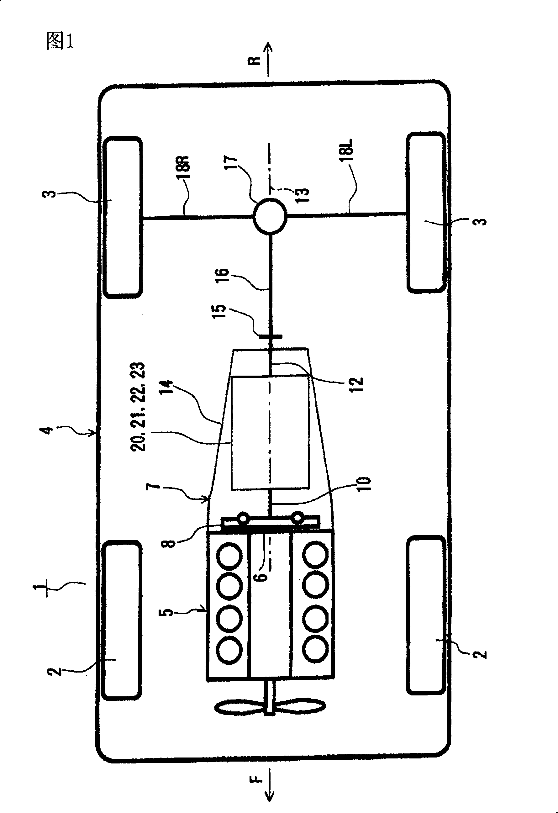
[0063] Hereinafter, embodiments of the present invention will be described with reference to the drawings. figure 1 An example of an automobile according to the present invention, that is, an automobile 1 equipped with a hybrid drive device according to the present invention is shown. The automobile 1 shown in this figure is a FR (front engine, rear wheel drive) type automobile, and this figure is a plan view typically showing its schematic configuration. In addition, in an actual automobile, the arrow F direction in the figure indicates the front side, and the arrow R direction indicates the rear side.

[0064] The automobile 1 shown in this figure has a vehicle body 4 supported by left and right front wheels 2, 2 and left and right rear wheels 3, 3 serving as drive wheels. On the front portion of the vehicle body 4 , the internal combustion engine 5 is mounted via rubber fittings (not shown) with its crankshaft 6 oriented in the front-rear direction. In addition, in this ...


PUM


Abstract

An output shaft is divided into a first output shaft and a second output shaft. Torque from a motive power distributing planetary gear is transferred to the first output shaft. The first output shaft is supported on partition walls by a both-end support structure via bearings. Assist torque from a transmission is applied to the second output shaft. The second output shaft is supported on partition walls by a both-end support structure via bearings.

Description

technical field [0001] The present invention relates to a hybrid drive device mounted on an automobile, and an automobile equipped with the same, and particularly relates to a hybrid drive device suitable for use in FR vehicles, in which an input shaft and an output shaft are arranged on a rotation center line. Background technique [0002] In the past, as a hybrid drive device, a so-called mechanical distribution type (separate type or dual motor type) device is known. This device uses a planetary gear, and each element is connected to the engine output shaft and transmitted to the control generator. (the first electric motor) and the output part of the wheel. In addition, the above-mentioned output part is connected to the driving (auxiliary) motor (second electric motor), and by controlling the above-mentioned generator, the engine output is automatically transferred from the above-mentioned planetary gear to the output part. Step speed change, and then the power of the o...

Claims


Application Information

Patent Timeline
Patent Type & Authority Patents(China)
IPC IPC(8): B60K6/20B60K6/36F16H3/72F16H61/32B60K6/26B60K6/365B60K6/405B60K6/445B60K6/547B60K17/04B60K17/06B60L50/16
CPCY02T10/6239F16H2200/2023F16H57/0037F16H2200/2007F16H3/728Y02T10/7258B60K1/02B60K6/54B60K6/365F16H2037/0873B60K6/405B60K6/445Y02T10/62Y02T10/72B60L15/20
Inventor 加纳成吾和久田聪尾崎和久池田利治石桥厚足立昌俊小嶋昌洋
Owner AISIN AW CO LTD
Why Eureka
Try Eureka