Multichannel electronic liquor-transferring system with standard signal interface

A standard signal, multi-channel technology, applied in the field of electronic medical devices, can solve the problems of increased mechanical structure complexity, low work efficiency, high cost, etc., and achieve the effect of easy automatic control, convenient secondary development, and high liquid absorption accuracy

Inactive Publication Date: 2009-09-09
JIANGSU UNIV
View PDF8 Cites 0 Cited by
  • Summary
  • Abstract
  • Description
  • Claims
  • Application Information

AI Technical Summary

Problems solved by technology

The disadvantages of this kind of pipette are: (1) The computer needs to have a built-in switch card and control program, and the technology is not universal; (2) The micro operation is realized by the liquid level detection device, which has high cost, and the mechanical vibration causes the pipette (3) It is a single-channel pipette, which can only transfer one liquid per operation, and the work efficiency is low
Its disadvantages are: (1) there is a special unloading tip mechanism inside, which increases the complexity of the mechanical structure; (2) it is a special automatic pipetting device, and its interface has a high degree of closure, which is not conducive to the promotion and use of the product, especially It is the secondary development of the product; (3) The instrument realizes the operation of installing the gun head through the sinking action of the manipulator, but its mechanical structure is rigidly matched and lacks protective measures. When the manipulator has a motion error in the horizontal plane (ie There is a position error between the axis of the tip column and the axis of the tip), which will often crush the tip of the pipette or the tip of the pipette

Method used


Image

  • Multichannel electronic liquor-transferring system with standard signal interface
  • Multichannel electronic liquor-transferring system with standard signal interface
  • Multichannel electronic liquor-transferring system with standard signal interface

Examples


Embodiment Construction

[0031] The present invention will be further described below in conjunction with accompanying drawing and embodiment:

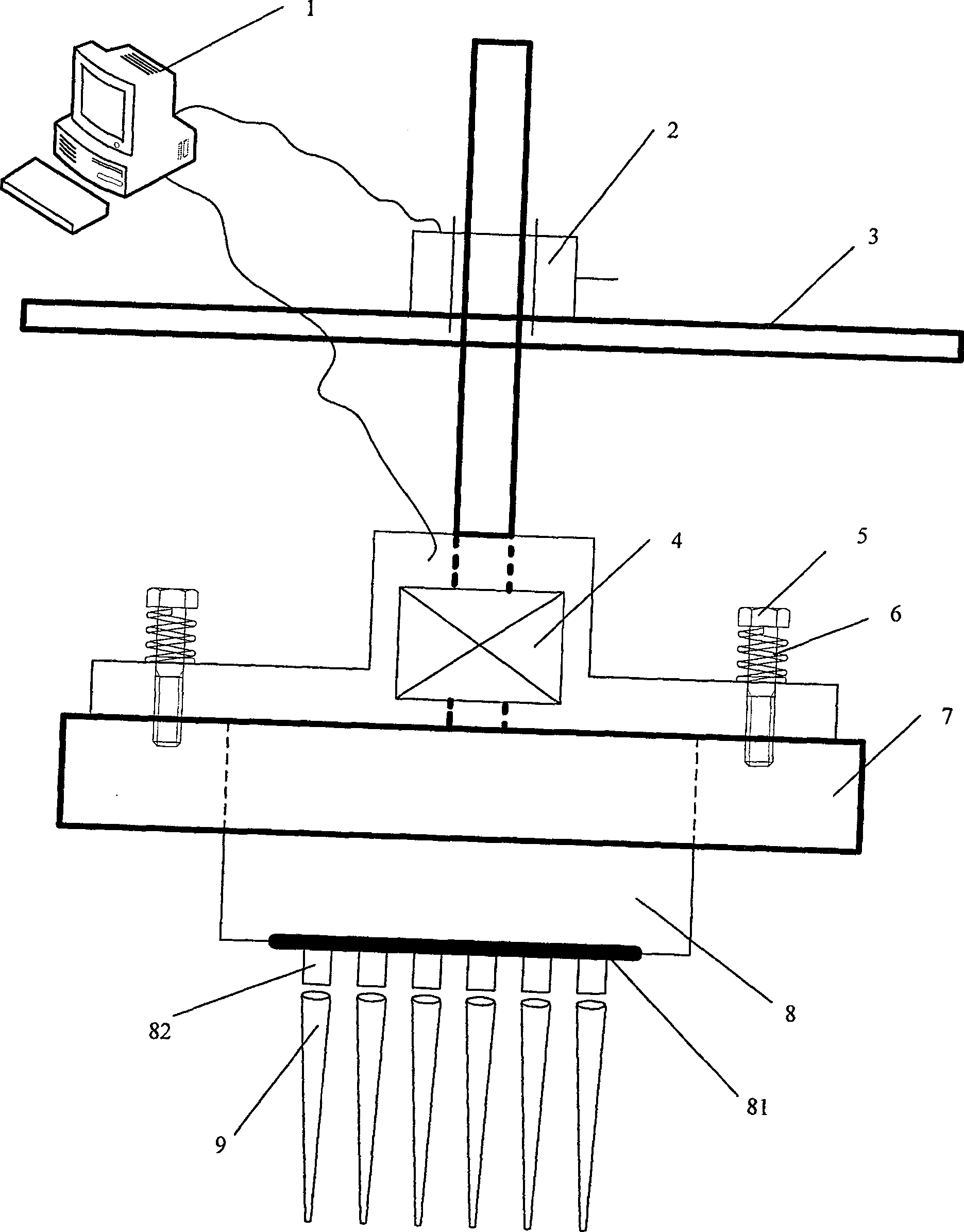
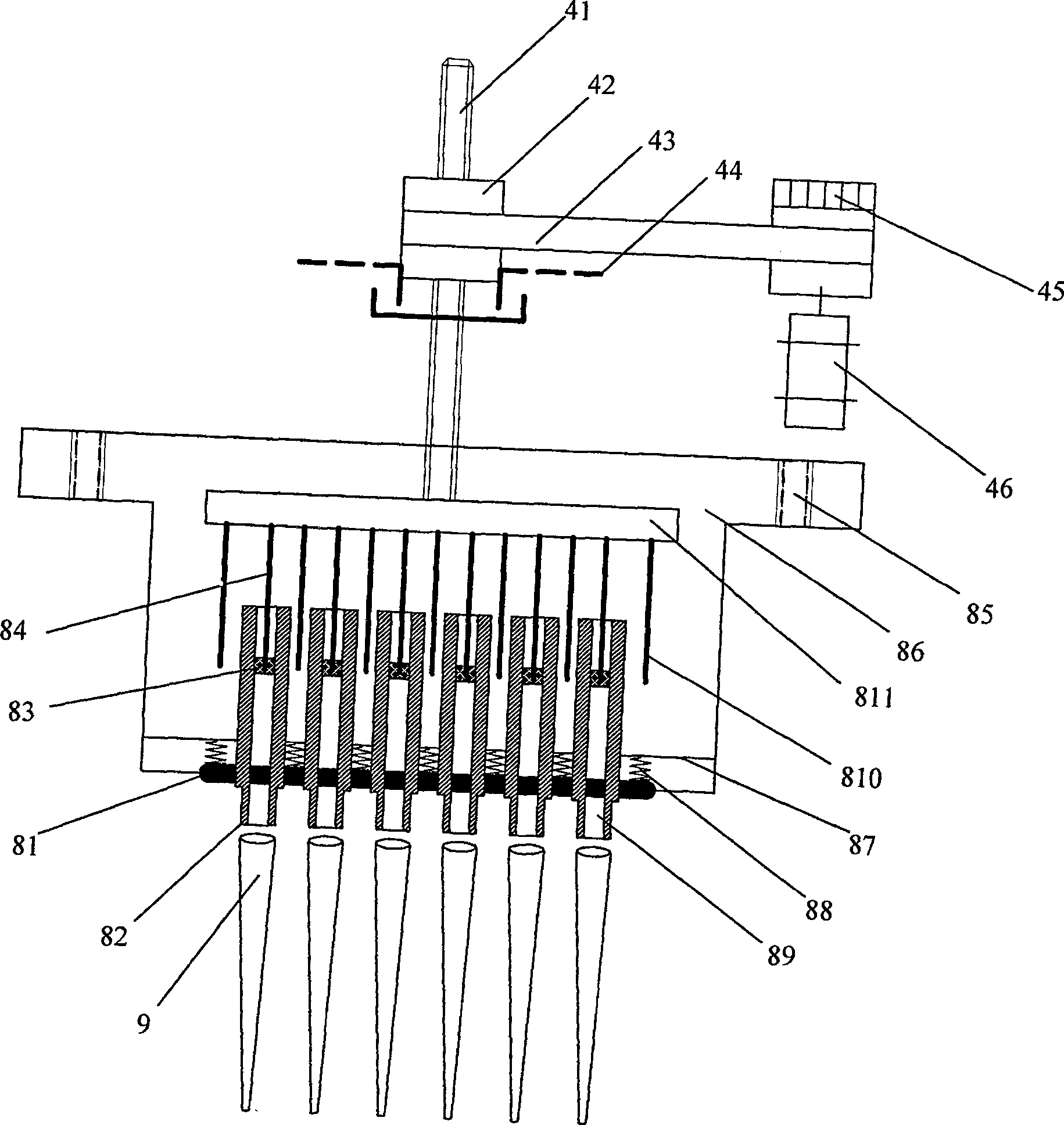
[0032] See attached figure 1 As shown, a 6-channel electronic liquid pipetting device provided by the present invention includes: a control computer 1, a carrying platform 3, a driving motor 2, a lifting platform 7, a pipette 8, an electromechanical movement unit 4 of the pipette, and a hexagonal bolt 5 , spring 6 and so on. It is characterized in that: the pipette 8 is fixed on the vertical lifting platform 7 by using the hexagonal bolt 5 and the spring 6; the computer 1 controls the drive motor 2 to make the lifting platform 7 move up and down; the carrying platform 3 can be horizontally positioned in the horizontal plane , longitudinal movement (not marked in the figure).

[0033] In this facility example, the pipette 8 adopts a syringe pump structure, that is, it is composed of a piston and a pump chamber. The computer 1 controls the lifting platform 7...


PUM


Abstract

A multi-channel electronic transfer system with a standard signal interface is provided with the same number of injection pumps with the channels; the upper end of the piston rod of each injection pump is fixed below a lat plate; gun tip posts with hollow structure in the same number of the injection pumps are arranged corresponding to the positions of the lower ends of the piston rods of each injection pump; a pump cavity is arranged in the gun tip post; a push plate with a through hole and a fixing plate are arranged on the system; the number and the position of the through holes are corresponding to the gun tip posts; the outer diameter of the gun tip posts passes through the fixing plate and the through hole of the push plate; the outlet at the lower end is sleeved and connected with the gun tip; the diameter of each through hole of the push plate is smaller than the outer diameter of the gun tip; a spring is arranged between the push plate and the fixing plate; the two ends of the spring are respectively and fixedly connected with the two plates; small holes are arranged on the location of the spring on the fixing plate; the position and the number of the small holes are corresponding to the push rods; the upper end of the push rod and the upper ends of each injection pump are all fixed below the same flat plate. The flat plate is driven by an electromechanical moving unit controlled by a computer.

Description

technical field [0001] The invention relates to chemical analysis quantitative liquid separation and liquid addition tools, in particular to a multi-channel electronic pipetting system with a standard signal interface, which is used to transfer trace liquids and is installed on instruments and used in conjunction with manipulators. It belongs to electronic medical equipment field. Background technique [0002] The electronic pipette is a common chemical analysis quantitative liquid separation and liquid addition tool at home and abroad. It is widely used in biological and chemical experiments, especially in the medical device industry. It can generally be divided into two types: hand-held pipettes and automatic pipetting devices. The former is to manually complete the basic actions of installing the tip, absorbing (blowing), and removing the tip, while the latter generally cooperates with the manipulator, relying on the three-dimensional movement of the manipulator and the ...

Claims


Application Information

Patent Timeline
Patent Type & Authority Patents(China)
IPC IPC(8): B01L3/02
Inventor 盛占石潘天红营胜
Owner JIANGSU UNIV
Why Eureka
Try Eureka