Multiple imaging range unit of optical imaging device with single aperture
An optical imaging and ranging device technology, applied in the field of depth information on the surface of an object, can solve problems such as unfavorable miniaturization, large space, occupation, etc., and achieve the effects of easy assembly, simple ranging algorithm, and compact system structure
- Summary
- Abstract
- Description
- Claims
- Application Information
AI Technical Summary
Problems solved by technology
Method used
Image
Examples
Embodiment 1
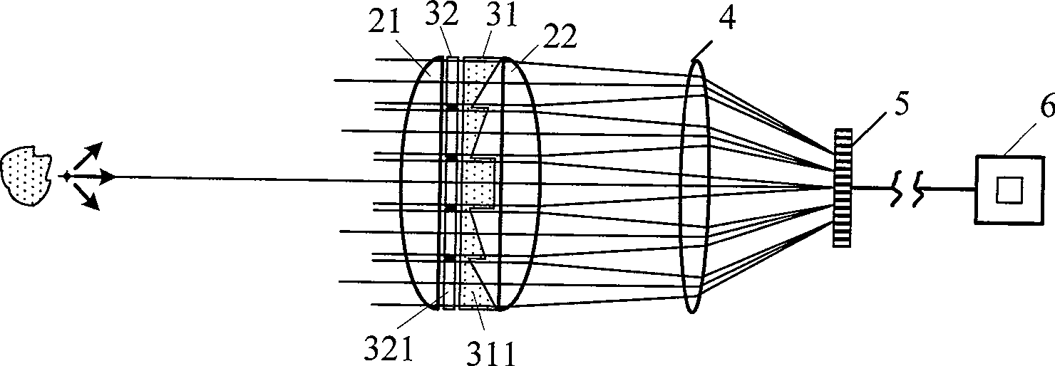
[0043] This embodiment is an image depth restoration technology based on monocular stereo vision. To restore image depth, it is necessary to obtain parallax images, that is, images obtained by observing the same object from various viewpoints. The multiple imaging mode of the device provides a method for acquiring multiple parallax images under single aperture imaging (monocular). Based on the principle of this embodiment, only the microprism array 31 is used as the multiple imaging element 3 . Such as image 3 As shown, the microprism array 31 sandwiched between the imaging main lens composed of two plano-convex lenses 21 and 22 has the effect of deflecting the split beams, and the vertex angle of each microprism 311 in the microprism array 31 is different, so that through The light beams of each microprism 311 are no longer focused on a point for imaging, but are separately focused. Each microprism 311 and lenses 21, 22 are combined into a single imaging system, just as th...
Embodiment 2
[0057] This embodiment is based on optical aperture coding three-dimensional imaging technology. The specific method is to code and arrange the microprism array 31 in a certain way to form a binary array. The number "0" in the coding array means that light is not transmitted here, and the number "1" means that a microprism 311 is placed here, and the vertex angle of each microprism 311 is still related to its position in the array. Due to the light-splitting effect of the microprism array 31, after a point source is imaged by the encoding prism array 31 and the imaging lens 2, the light intensity distribution on the image plane is a spot array scaled proportionally to the encoding array. The combined subsystem of each microprism 311 and the main imaging lens 2 is still imaging separately, and finally each sub-image is superimposed on the image receiving surface to form a coded image. According to the properties of the linear translation invariant system, the coded image I(r) ...
PUM
 Abstract
Description
Claims
Application Information
 - R&D
- Intellectual Property
- Life Sciences
- Materials
- Tech Scout
- Unparalleled Data Quality
- Higher Quality Content
- 60% Fewer Hallucinations
Browse by: Latest US Patents, China's latest patents, Technical Efficacy Thesaurus, Application Domain, Technology Topic, Popular Technical Reports.
© 2025 PatSnap. All rights reserved.Legal|Privacy policy|Modern Slavery Act Transparency Statement|Sitemap|About US| Contact US: help@patsnap.com


