Multiple imaging range unit of optical imaging device with single aperture

A technology of optical imaging and ranging device, which is applied in the field of depth information on the surface of objects, can solve the problems of occupation, large space, unfavorable miniaturization, etc., and achieve the effect of simple ranging algorithm, compact system structure and easy assembly

Inactive Publication Date: 2007-05-09
SHANGHAI INST OF OPTICS & FINE MECHANICS CHINESE ACAD OF SCI
View PDF0 Cites 20 Cited by
  • Summary
  • Abstract
  • Description
  • Claims
  • Application Information

AI Technical Summary

Problems solved by technology

This method requires multiple cameras to image the object at the same time, and the camera array needs to be arranged according to the aperture coding method, which occupies a large space and is not conducive to miniaturization and integration.

Method used


Image

  • Multiple imaging range unit of optical imaging device with single aperture
  • Multiple imaging range unit of optical imaging device with single aperture
  • Multiple imaging range unit of optical imaging device with single aperture

Examples


Embodiment 1

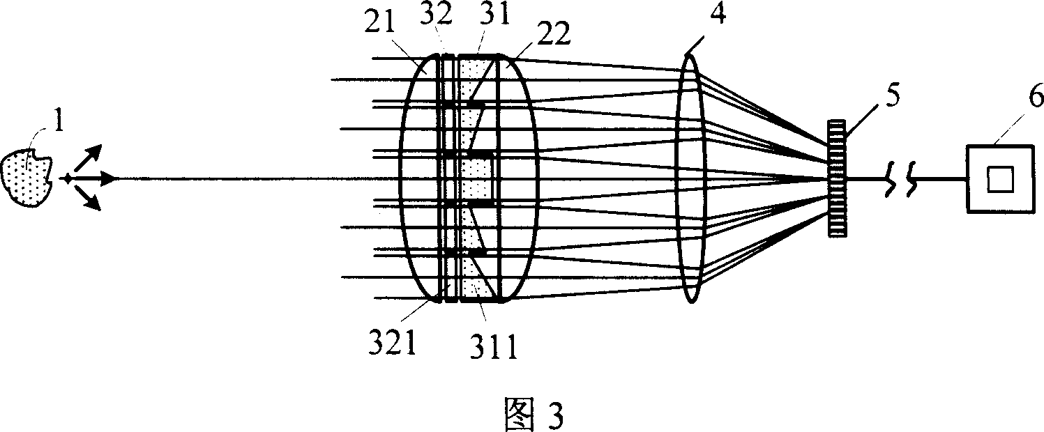
[0043] This embodiment is an image depth restoration technology based on monocular stereo vision. To restore image depth, it is necessary to obtain parallax images, that is, images obtained by observing the same object from various viewpoints. The multiple imaging mode of the device provides a method for acquiring multiple parallax images under single aperture imaging (monocular). Based on the principle of this embodiment, only the microprism array 31 is used as the multiple imaging element 3 . As shown in Figure 3, the microprism array 31 sandwiched between the imaging main lens formed by two plano-convex lenses 21 and 22 has the effect of deflecting the split beam, and the apex angle of each microprism 311 in the microprism array 31 is different , so that the light beam passing through each microprism 311 is no longer focused at one point for imaging, but is separately focused, and each microprism 311 and lenses 21, 22 are combined into a single imaging system, just like th...

Embodiment 2

[0057] This embodiment is based on optical aperture coding three-dimensional imaging technology. The specific method is to code and arrange the microprism array 31 in a certain way to form a binary array. The number "0" in the coding array means that light is not transmitted here, and the number "1" means that a microprism 311 is placed here, and the vertex angle of each microprism 311 is still related to its position in the array. Due to the light-splitting effect of the microprism array 31, after a point source is imaged by the encoding prism array 31 and the imaging lens 2, the light intensity distribution on the image plane is a spot array scaled proportionally to the encoding array. The combined subsystem of each microprism 311 and the main imaging lens 2 is still imaging separately, and finally each sub-image is superimposed on the image receiving surface to form a coded image. According to the properties of the linear translation invariant system, the coded image I(r) ...


PUM


Abstract

An optical imaging distance measuring device of single hole multiple imaging type is prepared as arranging master lens, multiple imaging element, field mirror and photoelectric detector in sequence on the same light axle, connecting output end of said detector to digital image process, sticking imaging master lens closely with multiple imaging element, using said processor to process digital image sampled by said detector and using data processing software to pick up depth information of object.

Description

technical field [0001] The invention relates to the depth information of the object surface, and is an optical imaging distance measuring device for measuring the depth information of the object surface in the field of view by single-aperture multiple imaging, that is, the distance between a point on the object surface and the viewpoint. The obtained distance information can be used for the reconstruction of the three-dimensional shape of the object, the recognition of target features, and the navigation of automatic vehicles and robots. Background technique [0002] The imaging process of ordinary optical imaging systems is generally the mapping from the three-dimensional object space to the two-dimensional image space, and the depth information of the scene is often lost in the imaging process. Obtaining the depth information of the image, that is, the distance from each point on the surface of the object to the viewpoint is very important in many applications. Commonly u...

Claims


Application Information

Patent Timeline
Patent Type & Authority Applications(China)
IPC IPC(8): G01C3/00G01C3/08G02B27/00
Inventor 阳庆国刘立人栾竹刘德安孙建锋
Owner SHANGHAI INST OF OPTICS & FINE MECHANICS CHINESE ACAD OF SCI
Why Eureka
Try Eureka