Electric lamp/reflector unit

A technology of reflectors and electric lamps, which is applied in the direction of reflectors, discharge lamps, lighting devices, etc., can solve the problems of lamp life and efficacy not being disclosed, and achieve the effect of good thermal conductivity

Inactive Publication Date: 2009-09-09
KONINKLIJKE PHILIPS ELECTRONICS NV
View PDF7 Cites 0 Cited by
  • Summary
  • Abstract
  • Description
  • Claims
  • Application Information

AI Technical Summary

Problems solved by technology

The lamp life and efficac...

Method used


Image

  • Electric lamp/reflector unit
  • Electric lamp/reflector unit
  • Electric lamp/reflector unit

Examples


Embodiment Construction

[0038] The figures are schematic representations only and are not drawn to scale. Especially for clarity, some dimensions are exaggerated to a high degree. In the drawings, wherever possible, like reference numbers refer to like parts.

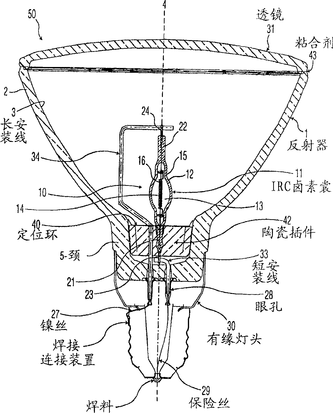
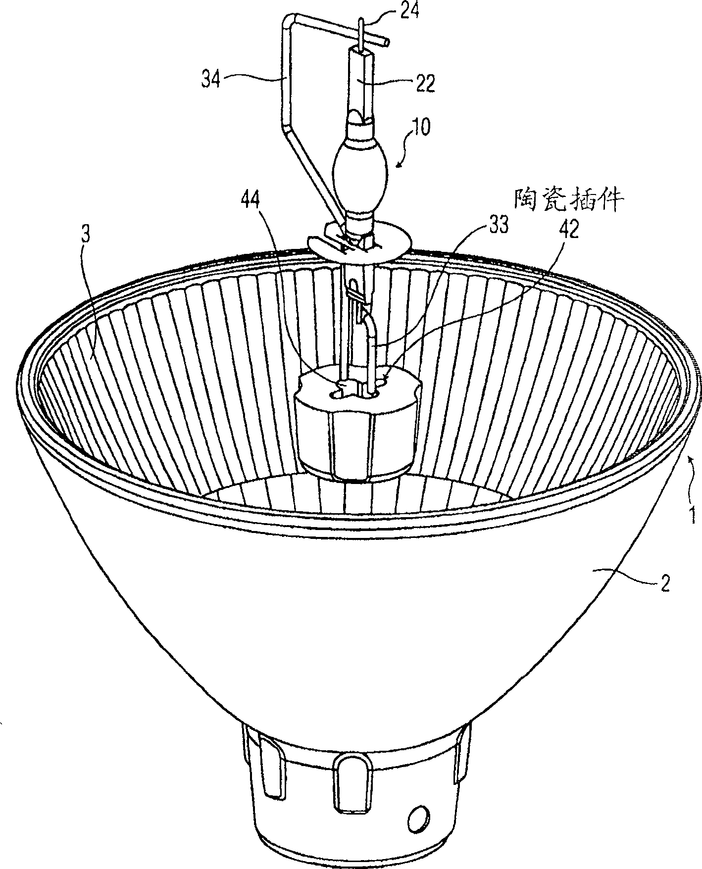
[0039] figure 1 A lamp / reflector arrangement according to the invention is shown in cross-section in FIG. As shown, the lamp / reflector arrangement 50 comprises a shaped reflector body 1 having a reflector portion 2 with a concave reflecting surface 3 and an optical axis 4 . A hollow neck portion 5 surrounding the optical axis 4 is integral with the reflector portion 2 . exist figure 1 In the example shown, the emission window of the reflector body 1 is closed by a curved lens 31 . In an alternative embodiment, said lens 31 is a planar lens. figure 1 The embodiment of the lamp / reflector arrangement shown in is a reflector body 1 of type PAR38.

[0040] The lamp / reflector arrangement further comprises an electric lamp 10 comprising a gas-...


PUM


Abstract

The present invention provides a new type PAR38 lamp/reflector assembly, which includes a halogen lamp suitable for 100 watts/120 volts, coated with an infrared film to reflect the infrared energy generated by the halogen lamp back to the filament, thereby making it More efficient; meeting and preferably exceeding the minimum EPACT efficacy criteria, having a median lifetime of at least about 3000 hours while giving a light output greater than 90% of the original value of about 1750 hours. This device comprises a double-capped electric lamp (10), which is arranged in the reflector body (1) so that the first end (21) is at least partly located in the neck portion (5), the cavity (13 ) is located in the reflector part (2), the electric light source (16) is mainly located on the optical axis (4), and during lamp operation, the seal located under the mounting ring (40) and through which the first end (21) passes The polished ceramic insert (42) effectively dissipates heat from the first end portion (21).

Description

technical field [0001] The invention relates to an electric lamp / reflector arrangement comprising a reflector body having a reflector part having a concave reflecting surface with an optical axis and integrally formed therewith A hollow neck-shaped portion around the optical axis, the electric lamp comprising: a quartz glass wall, a metal foil, a first end and a second end, wherein the quartz glass wall encloses a lamp having a geometric center, generally spherical or elliptical, of predetermined shape a cavity, the quartz glass wall is at least partially provided with a coating that reflects infrared rays and transmits visible light, the cavity houses a substantially linear electric light source, the metal foil is entirely inserted in the quartz glass wall and connected to the electric light source, The first end portion and the second end portion are arranged opposite to each other and each comprise a seal sealing a corresponding electrical conductor, which is connected to t...

Claims


Application Information

Patent Timeline
IPC IPC(8): H01K1/24H01K1/34H01K1/58H01K1/32H01J61/34H01J61/52F21V29/00F21V7/22F21Y101/00H01K1/44
CPCH01K1/44H01J61/34H01K1/325H01K1/24H01J61/361H01J61/35H01K1/36F21V7/22H01K1/58H01J61/523F21V29/004F21V7/28F21V7/24F21V29/503
Inventor J·惠扎V·于拉多A·罗佩兹
Owner KONINKLIJKE PHILIPS ELECTRONICS NV
Why Eureka
Try Eureka