Disposal radial artery compression hemostat

A technique for compressing hemostasis and radial artery, applied in the field of medical hemostatic devices, can solve the problems of increasing the pain of patients, inconvenient operation, and increasing the labor intensity of doctors, and achieves the effect of avoiding cross infection and improving hemostasis effect.

Active Publication Date: 2009-09-16
杭州艾力康医药科技有限公司
View PDF8 Cites 3 Cited by
  • Summary
  • Abstract
  • Description
  • Claims
  • Application Information

AI Technical Summary

Problems solved by technology

[0002] At present, the hemostasis of the radial artery after puncture still adopts the backward method of artificial finger pressure and bandaging. This is an empirical hemostasis method. If the pressure is too small, it is easy to cause bleeding; if the pressure is too high, it is easy to cause finger numbness and shaking, and even ischemia. , due to the use of manual pressure to stop bleeding, the strength of the implementation is not easy to maintain stable, often resulting in hemostasis failure, and it is necessary to press again to stop the bleeding. On the one hand, it increases the labor intensity of the doctor, and on the other hand, it also causes pain to the patient. Compression to the ulnar artery, due to the long duration of compression, can easily lead to arterial occlusion, and at the same time block the venous return, resulting in congestion and swelling of the hands, increasing the pain of the patient. In addition, multiple people are required to cooperate in the operation of compression to stop bleeding. Inconvenient and reduces work efficiency
[0003] There are also some instruments for hemostasis on the market, mainly including spiral type and air bag type, but in the process of implementation, due to the uncertainty of the incident, neither of them can effectively stop bleeding. Effect
Moreover, because most of the hemostats are used repeatedly, there is a hidden danger of cross-infection, which brings certain dangers to the recovery of the patient's body.

Method used


Image

  • Disposal radial artery compression hemostat

Examples


Embodiment Construction

[0009] The present invention will be described in further detail below in conjunction with the accompanying drawings and embodiments.

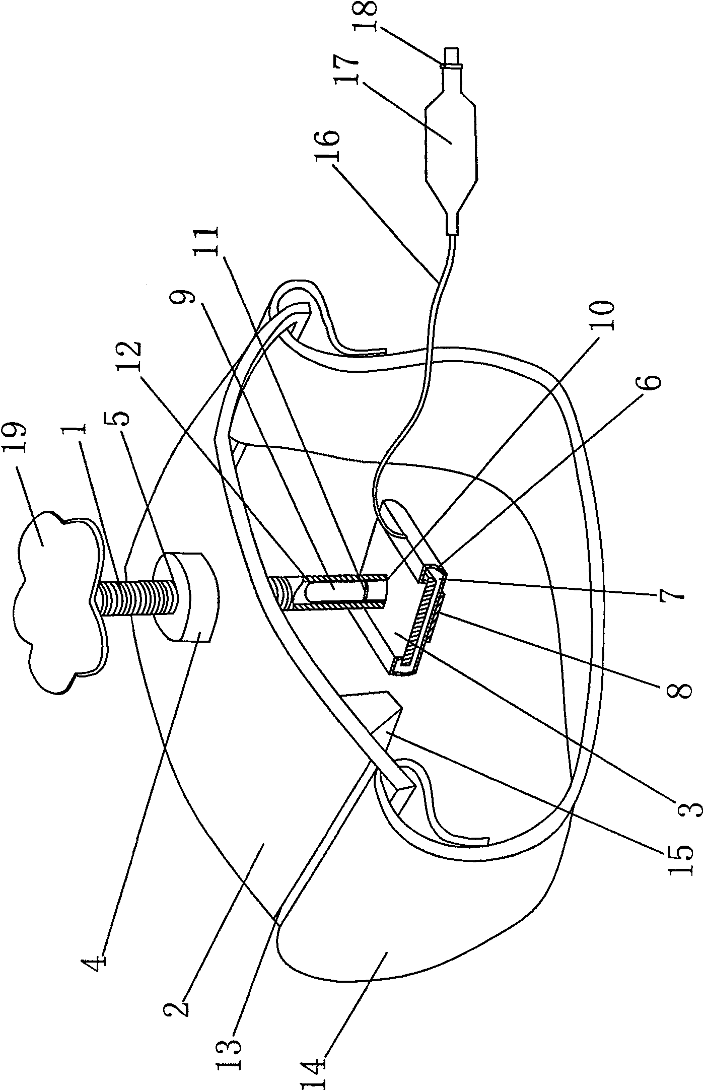
[0010] As shown in the figure, this disposable radial artery compression hemostat is mainly composed of a screw 1, a pressure regulating plate 2 and a pressure plate 3. The center of the pressure regulating plate 2 is provided with a bump 4, and the bump 4 is connected to the pressure regulating plate 2. As an integral structure, the bump 4 is provided with a screw hole 5, the screw 1 is screwed into the screw hole 5, the screw 1 is connected with a pressure plate 3, the upper end of the screw 1 is provided with a screw head 19, and by rotating the screw head 19, the The up and down movement of the screw rod 1 adjusts the position of the pressure plate 3 . A mandrel 9 is arranged on the top surface of the pressure plate 3, and a transverse protruding ring 11 is arranged on the mandrel 9, and a core hole 10 is opened at the lower end of the scr...


PUM


Abstract

The invention relates to a disposable radial artery compression hemostat, which is mainly composed of a screw rod, a pressure regulating plate and a pressure plate. The center of the pressure regulating plate is provided with a bump, and a screw hole is opened on the bump, and the screw rod is screwed into the screw hole. There is a pressure plate on the bottom, and the surrounding and bottom of the pressure plate are covered with a film. An air bag is formed between the film and the pressure plate. Gauze is arranged on the bottom of the film; With fixing strap. The beneficial effects of the present invention are: the disposable radial artery compression hemostat with this structure combines the original spiral type and the balloon type, which not only maintains the respective advantages of the two, but also overcomes the shortcomings of each other. Choose to use it in different situations, or use it at the same time to achieve better hemostatic effect. And at the same time, the bottom surface of the film is directly provided with gauze, and the used gauze cannot be used again, so that the hemostat cannot be used again, and the disposable use method avoids the risk of cross-infection caused by multiple uses.

Description

technical field [0001] The invention relates to a medical hemostat, which is mainly a disposable compression hemostat acting on the radial artery. Background technique [0002] At present, the hemostasis of the radial artery after puncture still adopts the backward method of artificial finger pressure and bandaging. This is an empirical hemostasis method. If the pressure is too small, it is easy to cause bleeding; if the pressure is too high, it is easy to cause finger numbness and shaking, and even ischemia. , due to the use of manual pressure to stop bleeding, the strength of the implementation is not easy to maintain stable, often resulting in hemostasis failure, and it is necessary to press again to stop the bleeding. On the one hand, it increases the labor intensity of the doctor, and on the other hand, it also causes pain to the patient. Compression to the ulnar artery, due to the long duration of compression, can easily lead to arterial occlusion, and at the same time...

Claims


Application Information

Patent Timeline
Patent Type & Authority Patents(China)
IPC IPC(8): A61B17/135
Inventor 郑隆泗
Owner 杭州艾力康医药科技有限公司
Why Eureka
Try Eureka