
Knife tool arc edging device

A technology of arc edge and cutting tool, which is applied in the direction of manufacturing tools, grinding machine parts, grinding/polishing equipment, etc. It can solve the problems of difficult arc negative chamfering, unsatisfactory sharpening quality, poor operating flexibility, etc. problem, to achieve uniform wear of the grinding wheel, convenient size and position adjustment, and improve the effect of sharpening quality

Inactive Publication Date: 2009-09-23
林志贺
View PDF10 Cites 0 Cited by
  • Summary
  • Abstract
  • Description
  • Claims
  • Application Information

AI Technical Summary

Problems solved by technology

At present, the rigidity of the main shaft of the traditional tool sharpening machine on the market is poor, the sharpening quality is not ideal, and the operation flexibility is also poor; in addition, when adjusting the sharpening angle, the height of the knife tip from the grinding wheel surface and the front and back will have a large difference. Changes, so that after adjusting the inclination angle, it is necessary to adjust the height of the tool tip and the front and rear feed position, especially when the inclination angle adjustment changes greatly, such as double relief angle; in addition, it is difficult to perform circular negative chamfering and blunt round edge grind

Method used


Image

  • Knife tool arc edging device
  • Knife tool arc edging device
  • Knife tool arc edging device

Examples


Embodiment 1

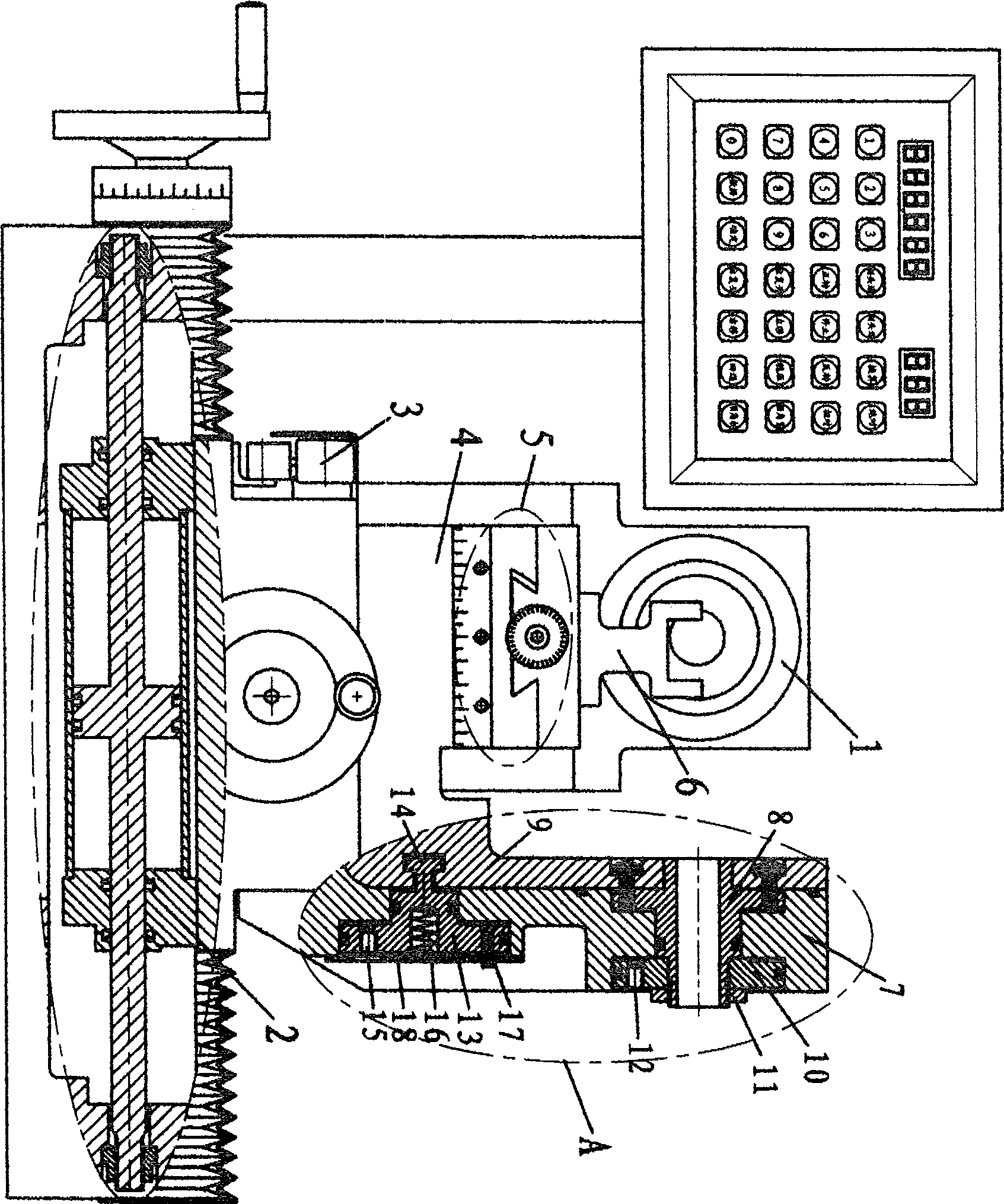
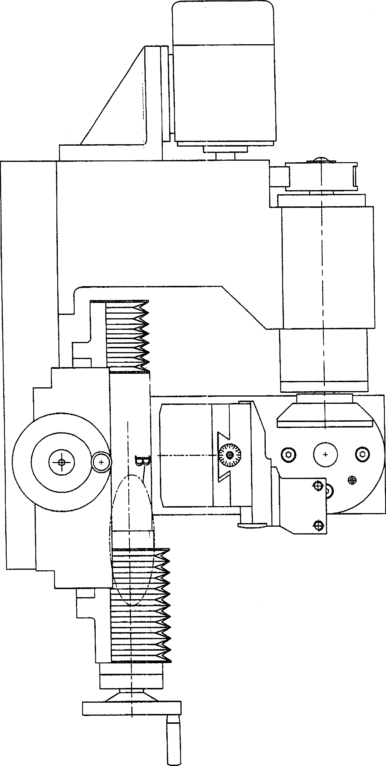
[0022] refer to figure 1 , 2 As shown, the grinding head assembly (1) of the present embodiment is integrally installed on the body, which can effectively improve the rigidity of the grinding head. The cross slide adopts a rolling guide rail structure, which has a small friction coefficient, stable movement, and high precision, which is especially beneficial to steady-pressure feed and low-speed reciprocating movement. A biaxial cylinder (2) and a set of clutch screw mechanism are installed in the longitudinal axis slide seat of the cross slide seat; When cutting the blade, separate the screw nut, and then use the double-axis cylinder (2) to perform automatic reciprocating motion; when sharpening milling cutters and other tools, connect the ventilation pipes at both ends of the double-axis cylinder (2) to the outside air, and then close the The screw nut is used to drive the screw when the screw is directly rotated, so that it is easy to operate. A screw adjustment mechanis...

Embodiment 2

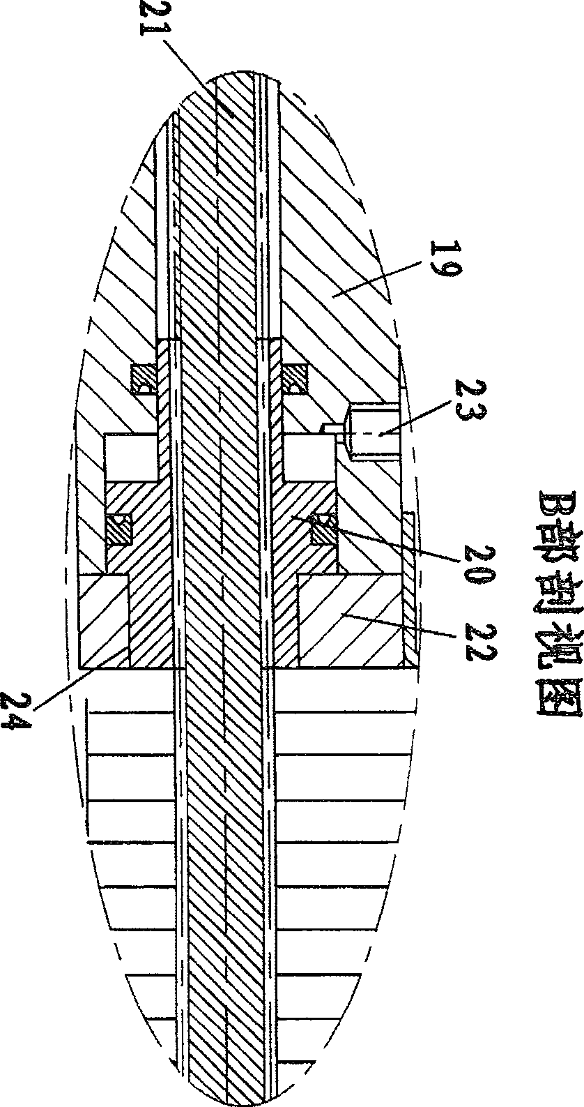
[0026] refer to Figure 5 As shown, in this embodiment and the first embodiment, a lifting mechanism is added between the inclination block of the inclination mechanism and the rotary table; and for the convenience of inclination adjustment, a worm transmission mechanism is installed between the rotary shaft and the support of the inclination mechanism ; In addition, the dual-axis cylinder and the clutch screw mechanism installed on the vertical axis slide seat are replaced with a transmission mechanism in which the stepping motor drives the rolling screw rod.

[0027] refer to Figure 5 , 6 As shown, the lifting mechanism of the present embodiment mainly consists of the inclination block (9) of the inclination mechanism, the base (25) of the rotary table, the gap adjustment block (26), the special nut bar (27), the special bolt (28), Bevel gear shaft (29), intermediate pin (30) form. The base of the rotary table (25) is processed with a dovetail protrusion in the direction...


PUM


Abstract

A cutter arc sharpening device. It is mainly composed of body, grinding head assembly, cross slide, inclination mechanism, rotary table, and tool rest; Between the sliding seat and the rotary table, the rotary table is equipped with an auxiliary cross slide seat, and a tool rest is installed on the auxiliary cross slide seat; the inclination axis of the inclination mechanism is 10 mm in radius from the extension line of the rotary axis of the rotary table. The height of the center of rotation of the end surface of the grinding wheel is within the range of half the outer diameter of the grinding wheel up and down. The cutter arc sharpening device has strong spindle rigidity, good sharpening quality and convenient adjustment, and is suitable for precision sharpening of machining tools.

Description

technical field [0001] The invention relates to a cutter arc device, in particular to a cutter arc sharpening device for machining a cutter. technical background [0002] With the popularization and application of cutting tools made of superhard materials such as diamond, cubic boron nitride, and ceramics, especially the new trend of turning grinding instead of grinding, people have become more and more demanding on the sharpening of turning tools. Traditional manual grinding of turning tools It has been difficult to meet the requirements, especially in terms of finish, which has prompted people to pay more and more attention to machine grinding tools. At present, the rigidity of the main shaft of the traditional tool sharpening machine on the market is poor, the sharpening quality is not ideal, and the operation flexibility is also poor; in addition, when adjusting the sharpening angle, the height of the knife tip from the grinding wheel surface and the front and back will ...

Claims


Application Information

Patent Timeline
Patent Type & Authority Patents(China)
IPC IPC(8): B24B3/58B24B41/04
Inventor 林志贺
Owner 林志贺
Learn More