Capillary pipe optical fibre and standard optical fibre connecting method

A standard optical fiber and connection method technology, applied in the direction of cladding optical fiber, optical waveguide light guide, optical waveguide coupling, etc., can solve the problems of different optical waveguide geometric shapes and different fiber cross-sectional area ratios, etc. Create easy effects

Inactive Publication Date: 2009-10-28
HARBIN ENG UNIV
View PDF6 Cites 1 Cited by
  • Summary
  • Abstract
  • Description
  • Claims
  • Application Information

AI Technical Summary

Problems solved by technology

For the new type of hollow capillary fiber whose core is a ring waveguide structure, the optical fiber to be connected has two main differences: (1) the area ratio of the fiber cross-section is different; (2) the geometric shape of the optical waveguide is different. , so there are many difficulties in the connection process

Method used


Image

  • Capillary pipe optical fibre and standard optical fibre connecting method
  • Capillary pipe optical fibre and standard optical fibre connecting method
  • Capillary pipe optical fibre and standard optical fibre connecting method

Examples


Embodiment ( 1

[0038] The present invention is realized in this way during the production and implementation process, including the following steps:

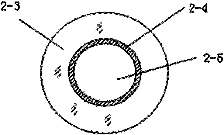
[0039] 1. Such as Figure 2-a For the hollow capillary fiber shown, peel off the coating layer at one end of it, and then clean it. During the cleaning process, avoid liquid entering the hollow cavity of the capillary fiber;

[0040] 2. Carefully cut out the flat capillary fiber end face;

[0041] 3. Prepare the fiber end of the standard physical single-core fiber to be connected according to the same steps as above;

[0042] 4. Cover the prepared section of quartz protective tube on one end of the standard single-core fiber or capillary fiber;

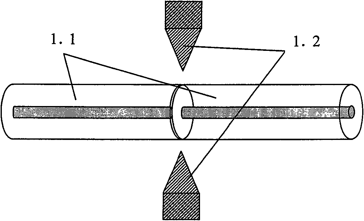
[0043] 5. Butt and weld the prepared two fiber ends in the fiber fusion splicer, such as figure 1 Shown

[0044] 6. In the implementation of fusion tapering, since the two optical fibers used have the same diameter, both are 125 microns. The softening point of the hollow capillary fiber material is the s...

Embodiment ( 2

[0048] The second embodiment of the present invention is implemented in this way during the production and implementation process, and includes the following steps:

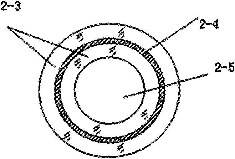
[0049] 1. Take as Figure 2-b For the hollow capillary fiber shown, peel off the coating layer at one end of it, and then clean it. During the cleaning process, avoid liquid entering the hollow cavity of the capillary fiber;

[0050] 2. Carefully cut out the flat capillary fiber end face;

[0051] 3. Prepare the fiber end of the standard physical single-core fiber to be connected according to the same steps as above;

[0052] 4. Cover the prepared section of quartz protective tube on one end of the standard single-core fiber or capillary fiber;

[0053] 5. Butt and weld the prepared two fiber ends in the fiber fusion splicer, such as figure 1 Shown

[0054] 6. In fact, when the tapering is melted, the two optical fibers used have the same diameter, both of which are 125 microns. The softening point of the hollow cap...


PUM


Abstract

The invention provides a connection method between a capillary optical fiber and a standard optical fiber. Strip off the coating layer of the capillary fiber and the standard single-mode or multi-mode fiber at one end, clean and cut a flat fiber end face, and then melt and weld it through an optical fiber welding machine. Preheat for Δt seconds at a distance of δ (δ ranges from 0.1 to 3.5 mm, and Δt ranges from 3 to 12 seconds), and then implements melting and tapering to form a tapered light energy distribution area. During the tapering process, the optical power is monitored at one end of the capillary fiber. When the waist of the cone is thinned until the optical power monitoring value reaches the maximum, the tapering is stopped to form a cone coupling area, and a quartz protective sleeve is coated on the cone coupling area. And seal the two ends of the quartz protective sleeve with the standard optical fiber and the capillary optical fiber. The invention solves the problem of connecting hollow capillary optical fibers with the same diameter and different ratios of cross-sectional areas to standard optical fibers, is easy to manufacture, and has high light wave conversion efficiency.

Description

(1) Technical field [0001] The invention relates to a method for connecting an optical fiber, in particular to a method for connecting a capillary fiber with a standard single-mode fiber or a multi-mode fiber. (2) Background technology [0002] Optical fiber connection technology is the most basic specialized technology in the field of optical fiber applications. The connection of optical fibers refers to the joining of the end faces of two optical fibers. The basic requirement for connection is to maximize the coupling and transition of light energy from the input fiber to the receiving fiber. In addition to requiring low connection loss and high return loss for optical fiber connection technology, it also requires stable performance and sufficient mechanical strength when the ambient temperature changes. Therefore, precise mechanical and optical design, processing and assembly are required to ensure high-precision matching of the two fiber ends. [0003] There are three main wa...

Claims


Application Information

Patent Timeline
Patent Type & Authority Patents(China)
IPC IPC(8): G02B6/255G02B6/24G02B6/02
Inventor 苑立波杨军朱晓亮
Owner HARBIN ENG UNIV
Why Eureka
Try Eureka