
Brake device for motorcycle

A brake device and brake caliper technology, which is applied to bicycle brakes, brake types, axial brakes, etc., can solve the problems of increased rear wheel inertia moment, etc., and achieve good shape, low cost, and few parts Effect

Inactive Publication Date: 2009-11-04
HONDA MOTOR CO LTD
View PDF4 Cites 0 Cited by
  • Summary
  • Abstract
  • Description
  • Claims
  • Application Information

AI Technical Summary

Problems solved by technology

Moreover, since the brake caliper for braking on the rear wheel side is installed on the swing arm behind the axle, and is at a position away from the swing center axis of the swing arm, the moment of inertia when the rear wheel rotates increases.

Method used


Image

  • Brake device for motorcycle
  • Brake device for motorcycle
  • Brake device for motorcycle

Examples


Embodiment Construction

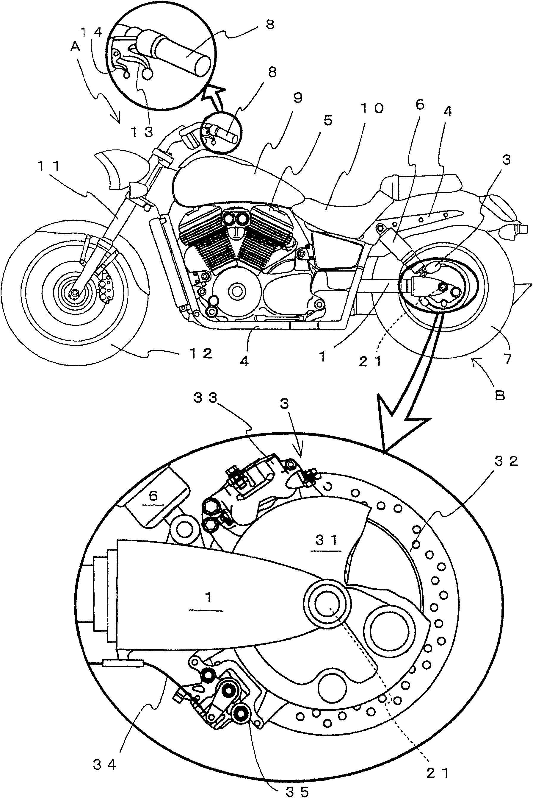
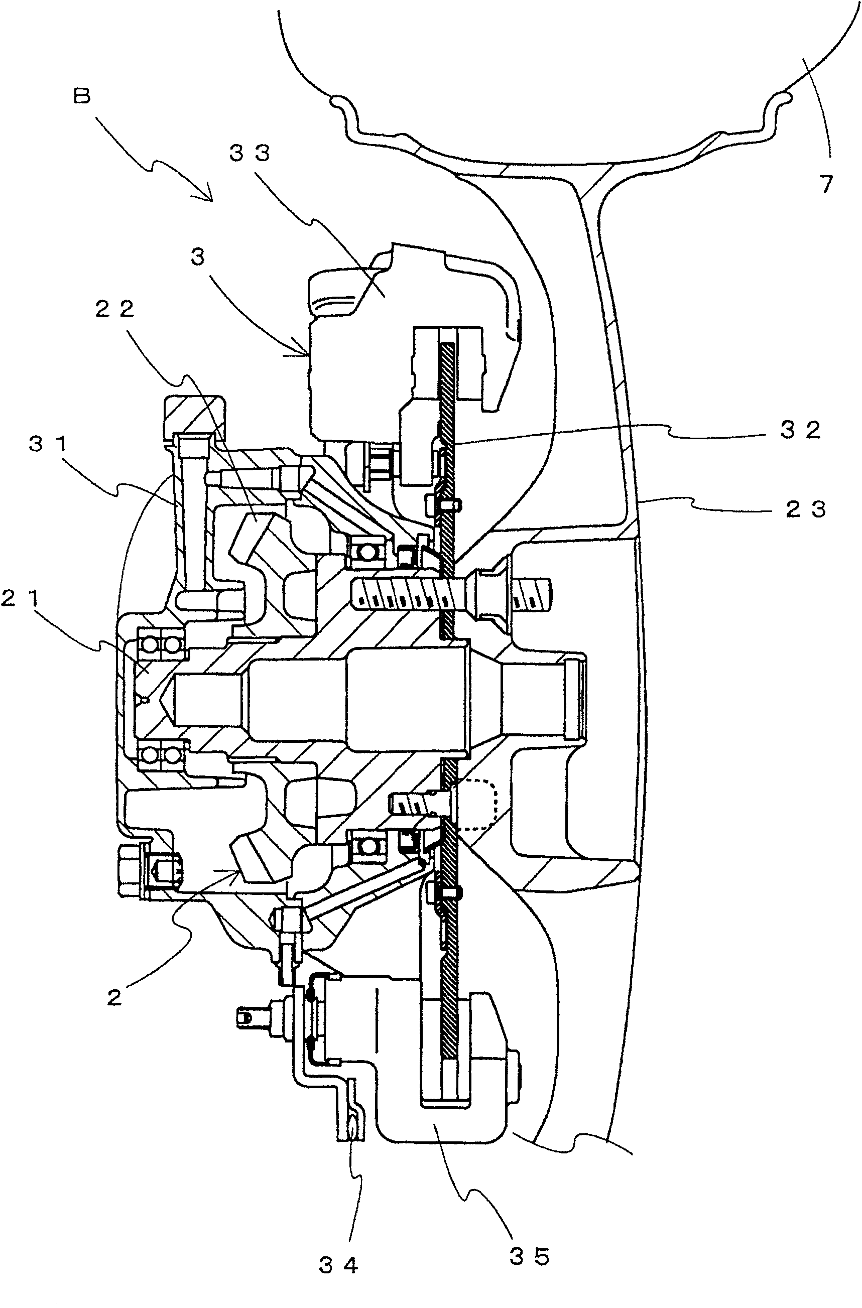
[0019] Hereinafter, embodiments of the braking device of the present invention will be described. Similarly, a state in which the brake device of this embodiment is incorporated into a motorcycle equipped with a vertical V-type engine is shown as an example, and detailed description of the main part, that is, the structure other than the brake device, is omitted. Likewise, reference numeral A in the figure represents a motorcycle, and reference numeral 3 represents a braking device.

[0020] The motorcycle A equipped with the braking device 3 of the present embodiment will be described. , shock absorber 6, rear wheel 7, joystick 8, fuel tank 9, driver's seat 10, front suspension 11 and front wheel 12.

[0021] The swing arm 1 is a bar-shaped part, which is swingably supported on a vehicle frame 4 designed in a required shape, and forms a cylindrical shape, and the drive shaft (not shown) that can transmit the rotary output output by the vertical V-type engine 5 is housed insi...


PUM


Abstract

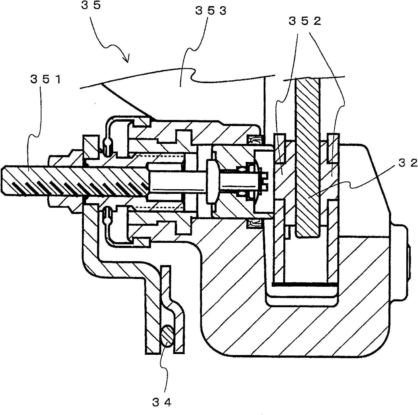
The invention provides a braking device which can properly maintain the followability of a swing arm to changes in the road surface and can be attached with a brake caliper for parking. A brake caliper (33) for braking and a brake caliper (35) for parking are separately arranged on the upper and lower sides of the swing arm (1), and are arranged in front of the axle shaft (21). At the same time, the brake caliper (35) for parking is arranged on the lower side of the swing arm (1), and the brake caliper (33) for braking is arranged on the upper side of the swing arm (1).

Description

technical field [0001] The present invention relates to a parking brake device for a motorcycle having a brake caliper and a parking caliper, and specifically relates to an improvement in the mounting position of each caliper. Background technique [0002] As a brake device for a motorcycle, a motorcycle provided with not only a brake device for braking but also a brake device for parking has been proposed. [0003] For example, in an automatic two-wheeled vehicle provided with such a parking brake device, a parking brake caliper is installed above the rear wheel shaft on a swing arm that supports the rear wheel swingably, and a brake caliper is installed below the joystick. There is a parking lever linked to the parking brake caliper. Furthermore, the brake caliper on the rear wheel side is provided on the lower side of the swing arm behind the axle (for example, refer to Patent Document 1). [0004] Patent Document 1: JP-A-2002-154469 (page 3, figure 2 ) [0005] The a...

Claims


Application Information

Patent Timeline
Patent Type & Authority Patents(China)
IPC IPC(8): B62L1/02
CPCF16D2125/40F16D55/226F16D2125/60F16D2121/02F16D2121/14
Inventor 石田慎一郎
Owner HONDA MOTOR CO LTD
Learn More