Surface luminescence device

A surface emitting, blue light technology, applied in luminescent materials, lighting devices, fluorescence and other directions, can solve the problems of low luminous efficiency white light LED, low luminous efficiency phosphor luminous conversion efficiency and other problems, achieve high luminous efficiency, excellent color rendering, high brightness effect

Inactive Publication Date: 2009-12-09
SHENZHEN JINYUEDA TECH
View PDF4 Cites 0 Cited by
  • Summary
  • Abstract
  • Description
  • Claims
  • Application Information

AI Technical Summary

Problems solved by technology

However, compared with the blue LED, the luminous efficiency of the violet LED or the ultraviolet LED itself and the luminous conversion efficiency for the phosphor are lower, so the luminous efficiency of the LED light-emitting device obtained by the second method is lower than that obtained by the first method. White LED Low

Method used


Image

  • Surface luminescence device
  • Surface luminescence device
  • Surface luminescence device

Examples


Embodiment 1

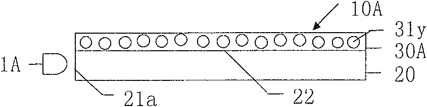
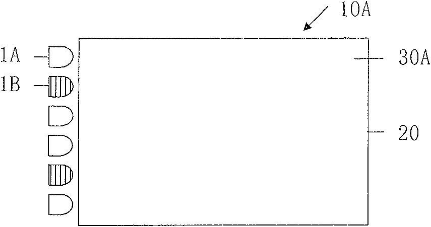
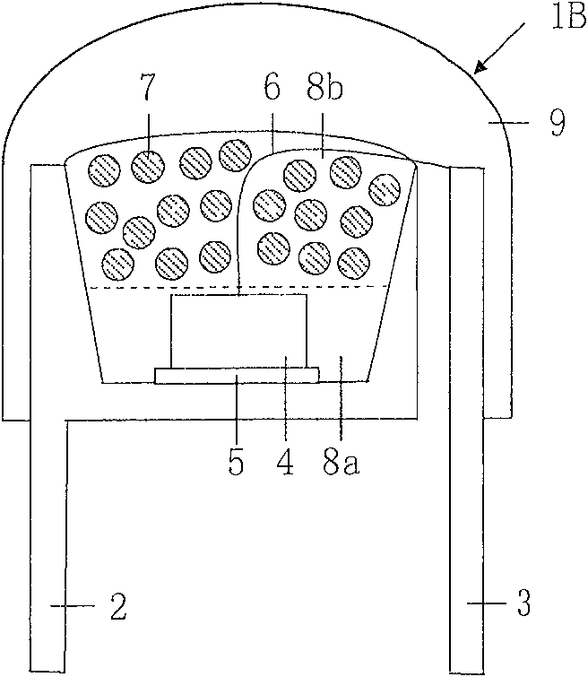
[0042] FIG. 1 shows a surface light-emitting device 10A of Example 1. As shown in FIG. FIG. 1( a ) and FIG. 1( b ) are views of the surface light-emitting device 10A viewed from one side and from the upper side, respectively. The surface emitting device 10A is composed of a plurality of blue LEDs 1A, a plurality of light-storing blue LEDs 1B, a light guide plate 20, a yellow phosphor layer 30A, a power supply and a circuit (not shown) for driving the LEDs 1A and 1B. figure 2 A cross-sectional view of LED1B is shown.

[0043] LED1B is composed of lead wires 2 and 3, ultraviolet LED chip 4 with a peak wavelength of 380nm, conductive glue 5, bonding wire 6, light-storing blue phosphor powder 7, resins 8a, 8b and sealing resin 9. A recess is provided on the lead wire 2, on which the ultraviolet LED chip 4 is placed. The ultraviolet LED chip 4 is electrically connected to the lead wire 2 through the conductive glue 5 , and is electrically connected to the lead wire 3 through the ...

Embodiment 2

[0050] FIG. 3 shows a surface emitting device 10B of Example 2. As shown in FIG. 3(a) and 3(b) are views of the surface light-emitting device 10B viewed from one side and the top, respectively. The difference from the surface-emitting device 10A of Embodiment 1 is that in the surface-emitting device 10B of Embodiment 2, the yellow phosphor layer 30A is arranged between LED1A, LED1B and the light-introducing surface 21 a of the light guide plate 20 . The rest are the same as those of the surface light-emitting device 10A.

[0051] When the surface light-emitting device 10B is working, first, blue light is emitted from LED1A and LED1B, part of the blue light is absorbed by the yellow phosphor 31y in the yellow phosphor layer 30A, and converted into yellow light by wavelength. The yellow light is mixed with the blue light without the wavelength conversion of the yellow fluorescent powder 31y to become white light, and then it is introduced into the light guide plate 20 from the ...

Embodiment 3

[0053] FIG. 4 shows a surface light-emitting device 10C of the third embodiment. 4(a) and 4(b) are views of the surface light-emitting device 10C viewed from one side and the top, respectively. The difference from the surface-emitting device 10B of Embodiment 2 is that in the surface-emitting device 10C of Embodiment 3, the LED 1A is disposed on the light-introducing surface 21a side (left side) of the light guide plate 20, and the violet LED 1C with a peak wavelength of 415nm is disposed On the side (right side) of the light introduction surface 21b of the light guide plate 20 . The phosphor layer consists of a yellow phosphor layer 30A and a white phosphor layer 30B, which are arranged between the LED 1A and the light-introducing surface 21 a of the light guide plate 20 and between the LED 1C and the light-introducing surface 21 b of the light guide plate 20 . The yellow phosphor layer 30A is the same as the yellow phosphor layer 30A in the surface emitting device 10A of th...


PUM


Abstract

The invention provides a LED surface luminous device with high luminescence efficiency, high luminance, good color rendering and light storing performance, and provides a light storing blue light LED used for a surface luminous device. The light storing blue light LED comprises an ultraviolet-violet rays LED chip, and light storing blue phosphor powder. The surface luminous device comprises two classes LEDs with different luminescence characters, and a phosphor powder layer formed of phosphor powder with different characters, the phosphor powder can have light storing performance, when the surface luminous device is operated, white light is generated through mixing the light emitted by the LED after the operation of the surface luminous device is stopped and the light emitted by the phosphor powder or only the light emitted by the phosphor powder, and after the operation of the surface luminous device is stopped, the light is unceasingly emitted with the light storing performance of the phosphor powder.

Description

technical field [0001] The present invention relates to surface emitting devices. Specifically, it relates to a surface emitting device having high luminous efficiency, good color rendering and light storage properties. Background technique [0002] Traditionally, fluorescent lamps, metal halide lamps, and incandescent lamps have been used in lighting devices. Although fluorescent lamps and metal halide lamps have high luminous efficiency, they contain harmful substances such as mercury, while incandescent lamps have low luminous efficiency, short life, and significant heat generation. In order to solve the above-mentioned problems in conventional light emitting devices, light emitting devices using LEDs have been proposed. LED has the following advantages: high luminous efficiency, less heat, because it is a solid light-emitting element, it will not burn the filament like an incandescent lamp, so it has a long life, and there is no harmful substances such as mercury, so it...

Claims


Application Information

Patent Timeline
Patent Type & Authority Patents(China)
IPC IPC(8): F21K2/00C09K11/80
CPCY02B20/181Y02B20/00
Inventor 邱行中尹绍刚邱励楠尹远成黎涤萍
Owner SHENZHEN JINYUEDA TECH
Why Eureka
Try Eureka