
Self-balancing rotary laser

A laser instrument and self-balancing technology, which is applied in the field of laser instruments, can solve the problems that the rotating laser instrument cannot be replaced, and the 360° reference line cannot be displayed, so as to achieve the effects of simplifying the structure, ensuring coaxiality, and ensuring safety

Active Publication Date: 2009-12-09
莱赛激光科技股份有限公司
View PDF8 Cites 0 Cited by
  • Summary
  • Abstract
  • Description
  • Claims
  • Application Information

AI Technical Summary

Problems solved by technology

However, the prism assembly of the reticle is fixed and cannot display a 360° reference line, so it cannot replace the rotating laser

Method used


Image

  • Self-balancing rotary laser
  • Self-balancing rotary laser
  • Self-balancing rotary laser

Examples


Embodiment 1

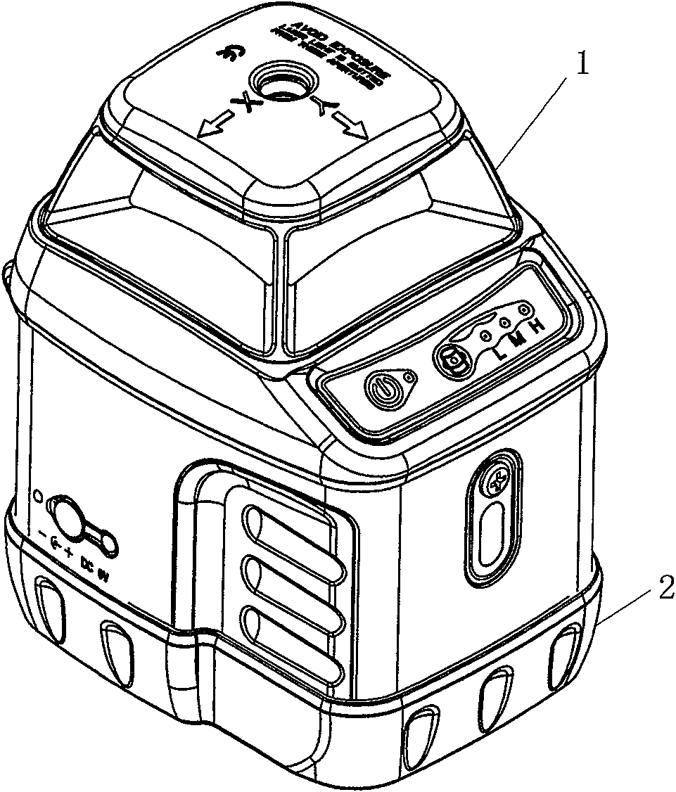
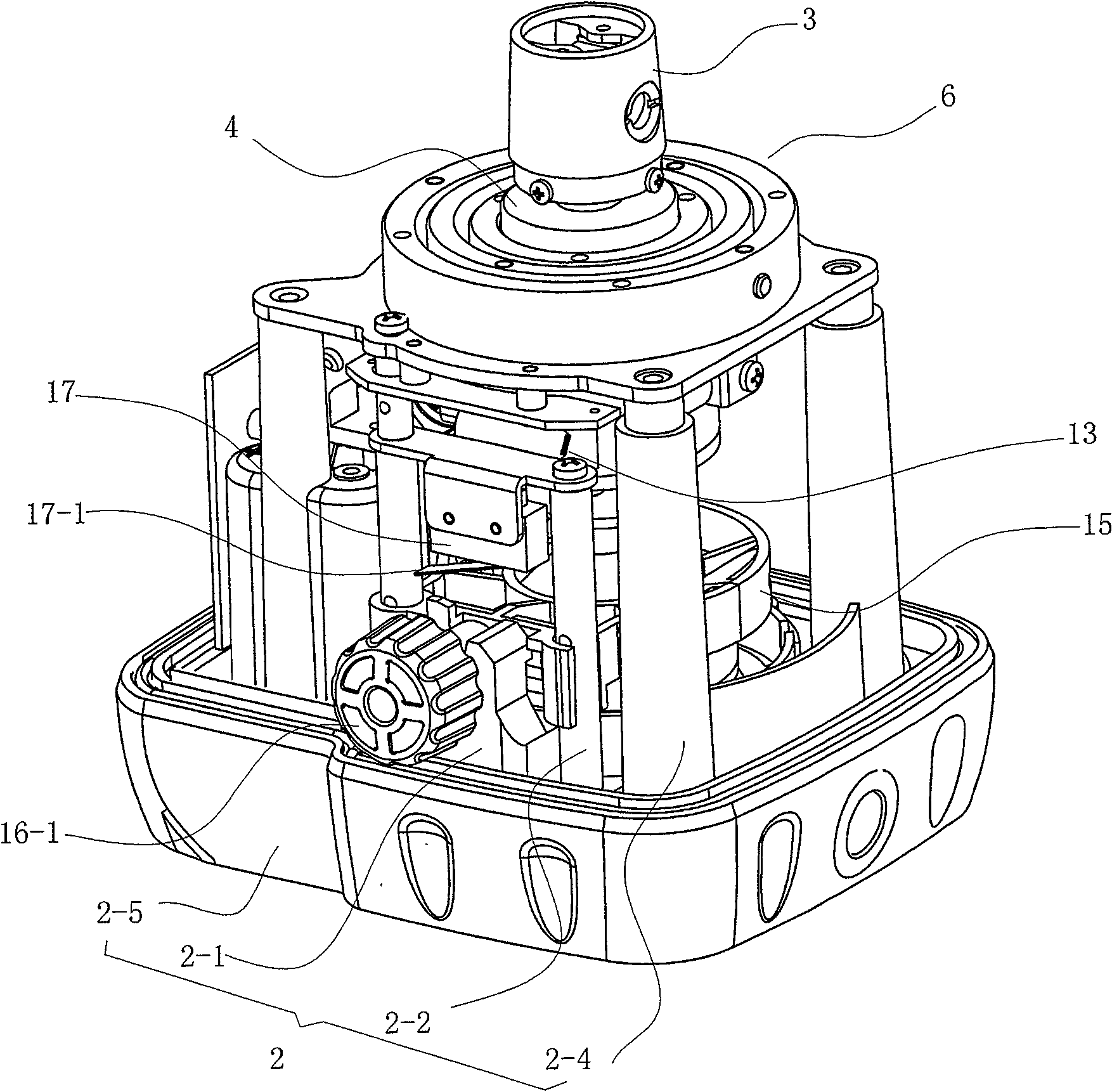
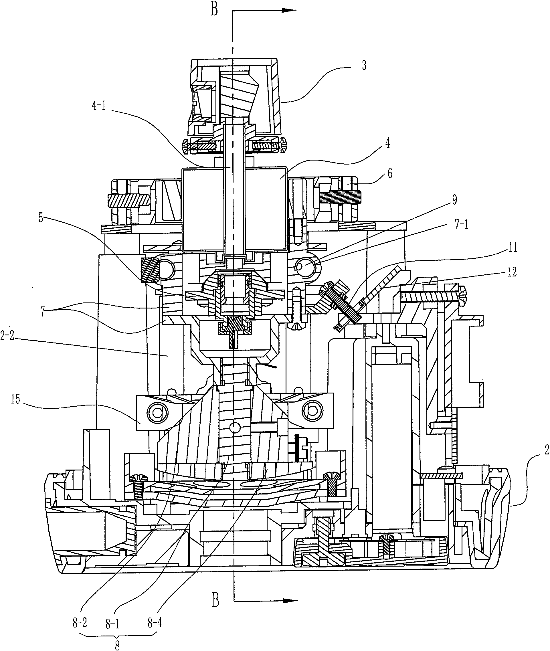
[0027] See Figure 2 to Figure 6 The illustrated embodiment 1 has a housing 1 , a frame 2 , a prism assembly 3 , a motor 4 , and a laser emitter 5 . The above-mentioned frame 2 has a base 2-5, on which a support column 2-4 and a guide rod 2-2 are arranged. The casing 1 and the base 2-5 of the frame 2 cooperate to form the casing of the laser instrument. The base 2-5 is provided with a battery pack to supply power to the motor 4 and the laser transmitter 5 . The laser instrument is equipped with a cardan shaft balance mechanism. The cardan shaft balance mechanism includes an annular component composed of inner, middle and outer rings, and the swing axis between the inner and middle rings is perpendicular to the swing axis between the middle and outer rings. 6 and the weight assembly 8 connected by the connecting piece 7 under the ring assembly. The weight assembly 8 has a central shaft 8-1 whose upper end is connected to the connector 7, and the lower end of the central shaf...

Embodiment 2

[0034] See Figure 7 and Figure 8, on the basis of Embodiment 1, one side of the housing composed of the casing 1 and the base 2-5 of the frame is detachably connected with a side-down base 18, and the seating plane of the side-down base 18 is connected to the frame base 2 The seating plane of -5 is vertical.

[0035] Two brackets 1-1 are arranged on this side of the housing, and a connecting rod 1-2 is fixed between the two brackets 1-1. The sideways base 18 has a bottom plate 18-1, and the bottom plate 18-1 is provided with two shaft frames 18-2 and a screw adjustment column 18-3, and a shaft is arranged between the two shaft frames 18-2, and a fastener is arranged on the shaft 19 and torsion spring 22, fastener 19 is provided with groove 19-1, respectively is provided with groove 18-21 on two shaft frames, groove 18-21 on two shaft frames and groove 19-1 on fastener 19 are in the same On the center line, but the opening directions of the slots 18-21 on the two axle fram...


PUM


Abstract

A self-balancing rotating laser instrument, the invention has a prism assembly, a motor, a laser emitter, and a cardan shaft balance mechanism composed of a ring assembly, a connector, and a weight assembly. The outer ring of the ring assembly is fixed on the frame, and the above-mentioned The main shaft of the motor is a hollow main shaft that runs through both ends. The hollow cavity of the main shaft is the optical channel. The motor is fixed in the inner ring of the ring assembly, the prism assembly is fixed on the top of the hollow main shaft of the motor, and the laser transmitter is fixed on the cardan shaft for balance. In the connecting part of the mechanism and opposite to the bottom end of the hollow main shaft of the motor, the laser beam emitted by the laser emitter passes through the hollow main shaft of the motor and emits through the prism assembly. The prism assembly, the motor, and the laser emitting assembly of the present invention are arranged in a vertical line, and the centers of gravity of the three are on the same straight line. Therefore, the self-balancing function of the laser instrument can be realized through the cardan shaft balancing mechanism. Moreover, the prism assembly is directly connected with the motor, omitting the transmission mechanism, and simplifying the structure of the laser instrument.

Description

technical field [0001] The invention relates to a laser instrument which can provide a reference line. Background technique [0002] When setting out in construction, decoration and decoration projects, it is necessary to mark the datum line on the working surface. The rotating laser, that is, the laser leveling instrument, can display a 360° reference line, so its prism assembly needs to be driven by a motor to rotate, and the laser beam emitted by the laser generator marks the reference line on the surrounding blocking surface through the rotating prism assembly. Since there is a space for light to pass between the laser generator and the prism assembly, the motor can only be arranged on one side of the prism generator, so that the motor needs to be connected with the prism assembly by a transmission mechanism. For example, the laser leveling instrument disclosed in the utility model patent specification of Chinese Patent No. 96241591.X is composed of a frame, a fuselage ...

Claims


Application Information

Patent Timeline
Patent Type & Authority Patents(China)
IPC IPC(8): G01C15/00
Inventor 陆建红
Owner 莱赛激光科技股份有限公司
Learn More