
Heat exchanger, especially gas cooler

A heat exchanger and gas cooling technology, applied in the direction of heat exchange equipment, heat exchanger type, heat exchanger shell, etc., can solve problems such as increasing the manufacturing cost of heat exchangers

Inactive Publication Date: 2009-12-23
BEHR GMBH & CO KG
View PDF8 Cites 0 Cited by
  • Summary
  • Abstract
  • Description
  • Claims
  • Application Information

AI Technical Summary

Problems solved by technology

Even in this form of construction, at least one part of the header is formed by compression molding or other costly forming methods, which increase the manufacturing cost of heat exchangers such as gas coolers

Method used


Image

  • Heat exchanger, especially gas cooler
  • Heat exchanger, especially gas cooler
  • Heat exchanger, especially gas cooler

Examples


Embodiment Construction

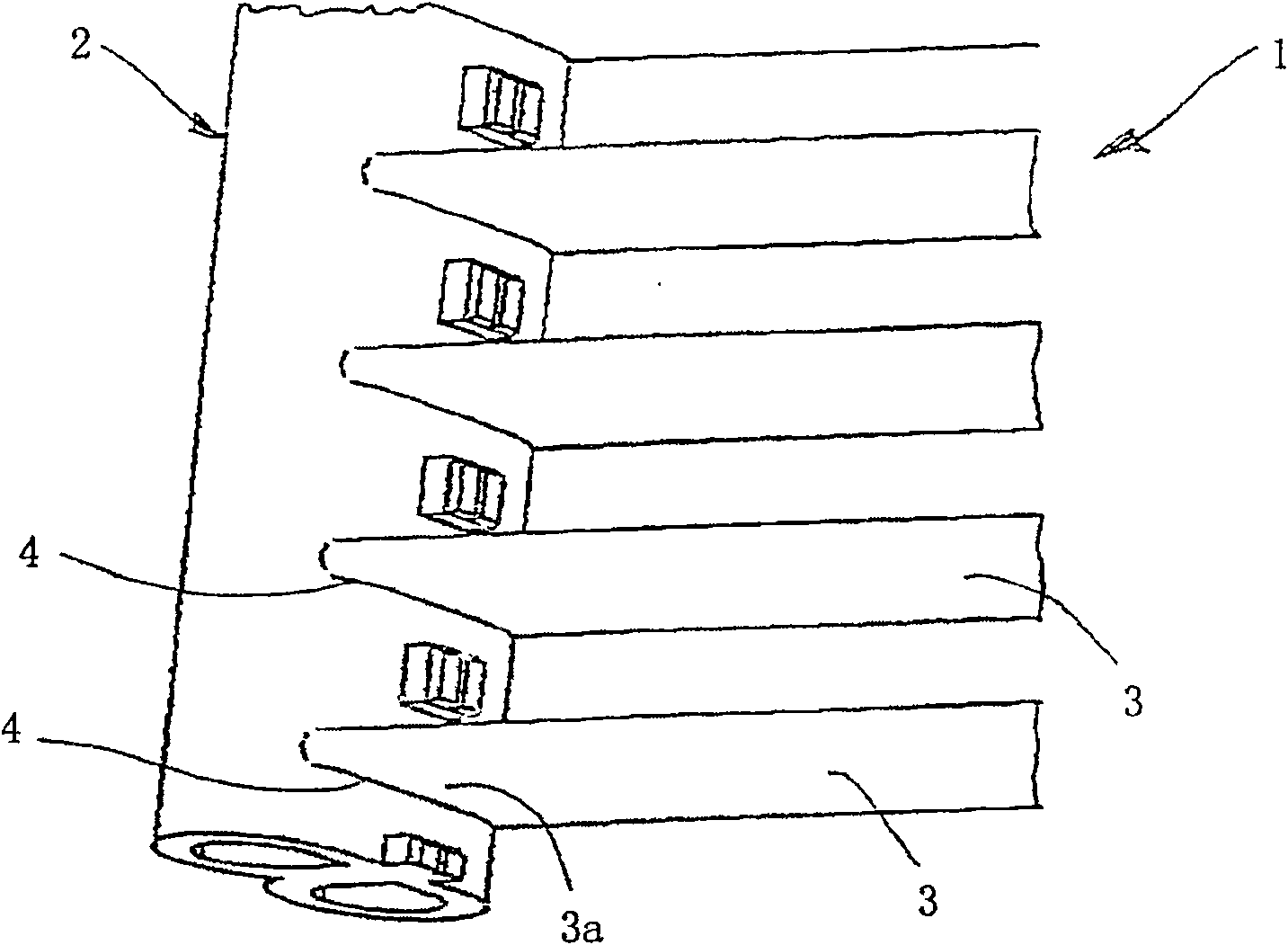
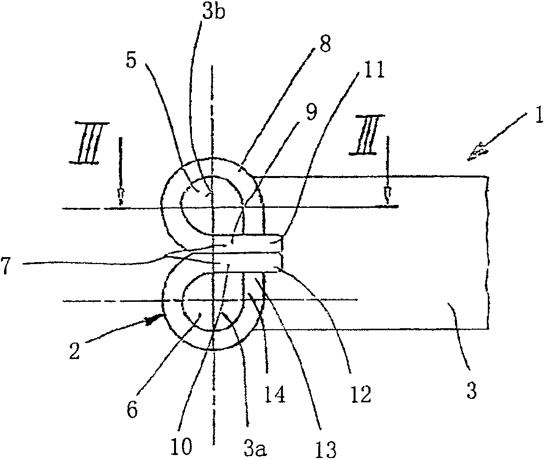
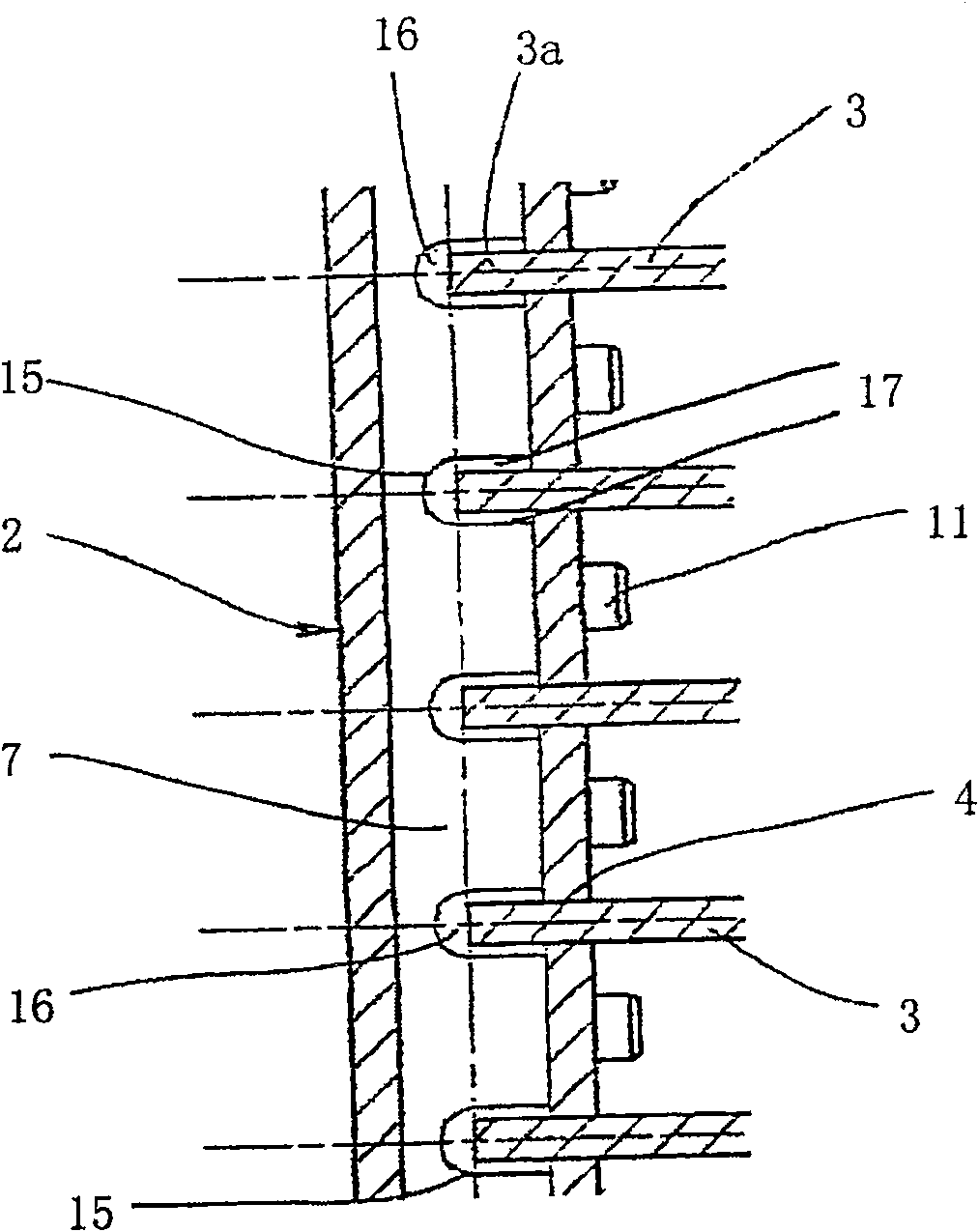
[0021] figure 1 A section of a gas cooler 1 is shown with a collector 2 and flat tubes 3 , the ends 3 a of which lead into the collector 2 and engage in slot-shaped openings 4 . Corrugated fins (not shown) are arranged between the flat tubes 3 to increase the heat exchange area with the air. The gas cooler 1 is especially suitable for use with CO 2 It is used as a refrigerant in the refrigerant cycle of automobile air-conditioning equipment, and of course its use is not limited to this. Mainly gaseous CO at a pressure of about 120 bar 2 The air flows through the gas cooler, ie in the collectors and flat tubes; secondly, the air brushes over the surface of the gas cooler. The gas cooler will CO 2 The temperature of the gas drops from about 150 degrees Celsius to 50 degrees Celsius. The pressure that occurs here is roughly equivalent to 10 times the pressure in the refrigerant cycle using R134a as the refrigerant in the traditional condenser.

[0022] figure 2 for figur...


PUM


Abstract

The heat exchanger has at least one manifold (2) divided into longitudinal channels and a row of flat pipes (3) with ends (3a) accommodated in openings (4) in the manifold and in fluidic connection with the channels. The manifold is made by bending from a prefabricated sheet strip with longitudinal edges with tongues and a central connecting region with cut-outs.

Description

technical field [0001] The invention relates to a heat exchanger, in particular to a CO 2 Gas cooler with refrigerant cycle. Background technique [0002] Heat exchangers for air conditioning equipment using R134a as refrigerant, especially condensers, consisting of a heat exchanger tube system with flat tubes and circular or other Shaped headers. Other heat exchangers for air-conditioning equipment, such as the double-column evaporator described in German patent DE-A198 26 881, have a collector divided into two longitudinal collecting chambers, which are preferably made of a prefabricated sheet, The edges of the sheet are partially bent during fabrication. This results in a centrally located double-layer longitudinal partition, which is fastened via tongues in openings in the base plate of the current collector. Two rows of openings are arranged on the bottom plate to configure two rows of flat tubes, that is, each longitudinal header chamber is connected by a row of fl...

Claims


Application Information

Patent Timeline
Patent Type & Authority Patents(China)
IPC IPC(8): F28F9/02F28F9/04F28D1/00F28D1/053
CPCF28F9/0214F28D2021/0073F28D1/0535
Inventor 乌韦·弗尔斯特库尔特·莫尔特
Owner BEHR GMBH & CO KG
Learn More