
Pile-roller up-rolling transfer type carding method and equipment

A transfer-type, carding technology, which is applied in deburring devices, textiles and papermaking, fiber processing, etc., can solve the problems of losing fiber humidity, affecting extraction rate, and difficult operation, so as to maintain fiber humidity, process adjustment is convenient, The effect of high fluff extraction rate

Inactive Publication Date: 2010-01-06
苗青 +1
View PDF3 Cites 0 Cited by
  • Summary
  • Abstract
  • Description
  • Claims
  • Application Information

AI Technical Summary

Problems solved by technology

For example, "Licker-in carding--Boundary layer air flow cutting and transfer method and equipment" and "Licker-in carding-Fan suction transfer method and equipment" can complete the coarse and impurity removal process of carding well. However, when the combed fluff is transferred due to the wind force, it will generate static electricity, quickly lose the humidity in the fiber, and produce hair particles, especially when the coarse hair, impurities and fluff that have not been combed are mixed and entangled. After the wool grains are formed together, it will affect the effect of the next step of carding. At the same time, when the wool grains are continued to be carded in the next process, the wool grains must be combed again, which will cause greater fiber damage.
Another example is "the licker-in carding method and equipment". On the one hand, the fluff after being carded by the carding roller is affected by the reverse airflow generated by the lower part of the large cylinder transfer carding roller. At the same time, some useful fluff is blown down, which affects the extraction rate and causes high consumption; on the other hand, it consumes a lot of power, occupies a large area, and the equipment is relatively complicated, difficult to operate, and troublesome to maintain.
Secondly, repeated carding between the cover plate and the cylinder transfer roller will cause unnecessary fiber damage, especially when it is necessary to repeatedly card, remove roughness, and remove impurities in order to achieve the purpose of obtaining high-quality finished cashmere. The equipment is even more damaged, the extraction rate is low, the consumption is large, the power consumption is large, and the operation is difficult, so that the target of the production product cannot be achieved.

Method used


Image

  • Pile-roller up-rolling transfer type carding method and equipment
  • Pile-roller up-rolling transfer type carding method and equipment
  • Pile-roller up-rolling transfer type carding method and equipment

Examples


Embodiment 1

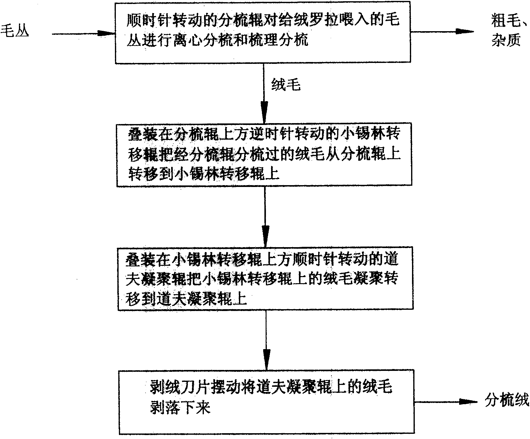
[0033] see figure 1 , a stacked roller upward transfer type carding method, the method is to stack the carding roller, small cylinder transfer, and doffer condensing roller sequentially from bottom to top, and the fluff after carding by the carding roller is from bottom to top Shift output up. Firstly, the carding roller rotating clockwise performs centrifugal carding and carding on the wool clump fed by the velvet roller to remove the coarse hair and impurities in the clump of wool. It runs upward; then the small cylinder transfer roller stacked above the carding roller and rotates counterclockwise will pick up the fluff hanging on the card clothing of the carding roller and transfer it upwards to the small cylinder transfer roller card clothing, and the fluff will follow The small cylinder transfer roller runs upward; then the doffer agglomeration transfer roller stacked on the top of the small cylinder transfer roller and rotates clockwise transfers the fluff agglomerated ...

Embodiment 2

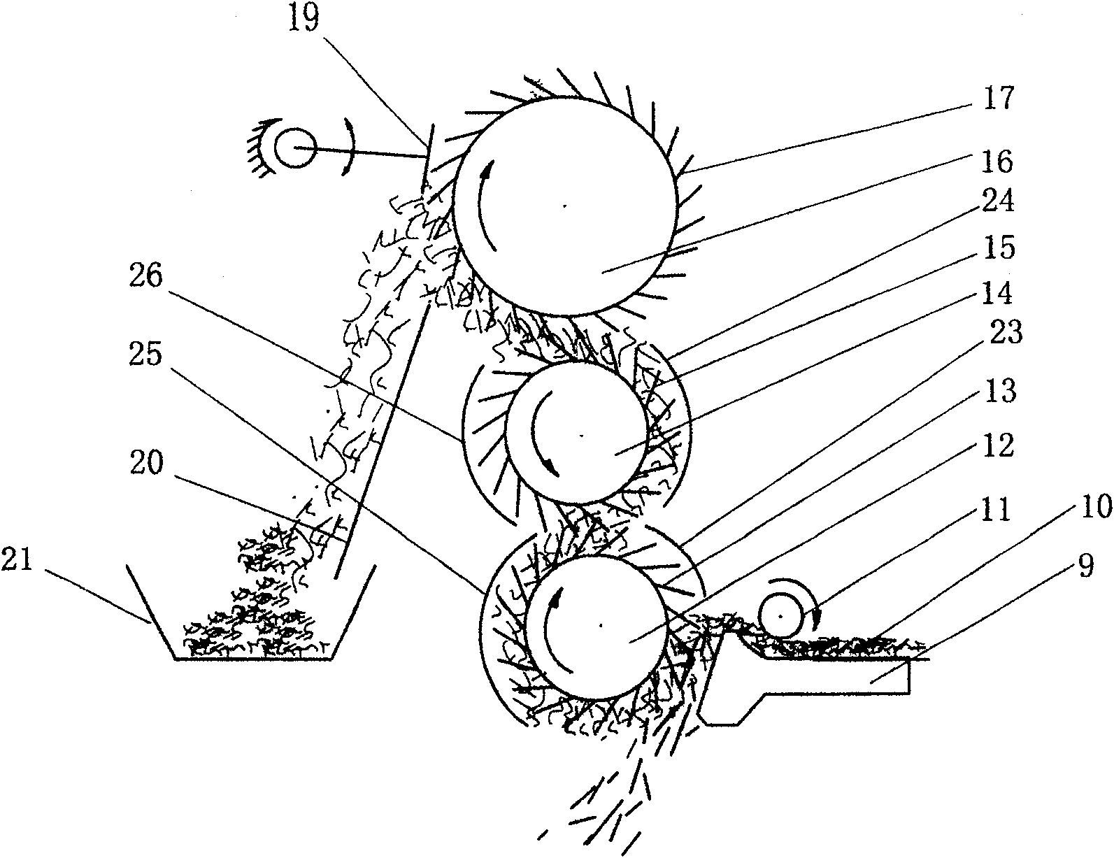
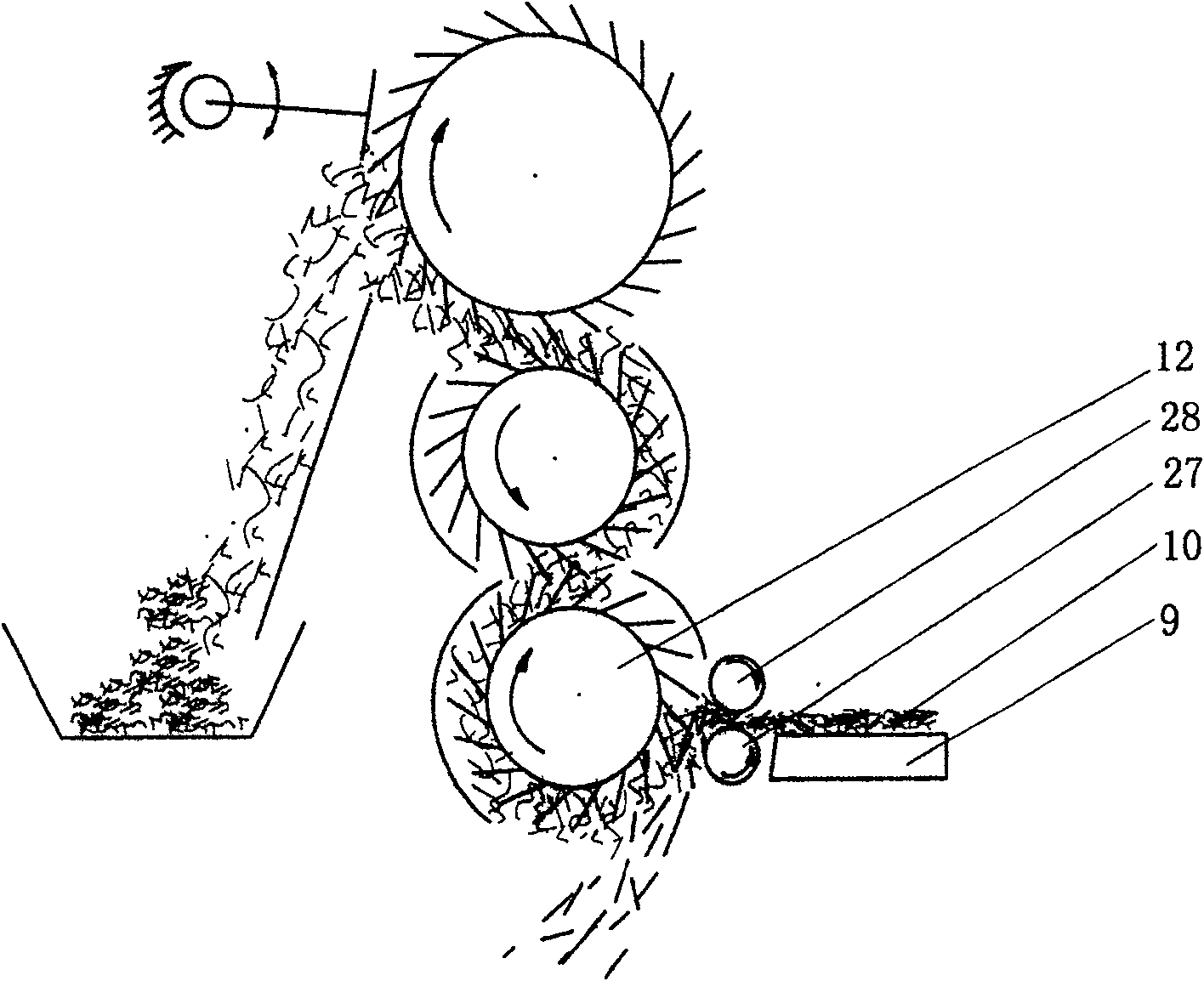
[0039] see figure 2 , a kind of upward stacking transfer type carding equipment, comprising a frame (not shown in the figure), a transmission mechanism (not shown in the figure), on the frame, carding rollers 12, A small cylinder transfer roller 14, a doffer condensing roller 16, and a cashmere feeding roller 11 are arranged in front of the carding roller 12; The front side; The frame is also provided with a swing type stripping suede blade 19, and this swing type stripped suede blade 19 is arranged on the doffer coagulation roller 16 rears.

[0040] Described transmission mechanism provides power transmission for the operation of carding roller 12, small cylinder transfer roller 14, doffer agglomeration roller 16, cashmere feeding roller 11, swing type stripping suede blade 19, and this transmission mechanism is prior art in this area, No longer.

[0041] In the present embodiment, a feeder roller 11 is installed in front of the opening roller 12, and the pile 10 is placed...

Embodiment 3

[0048] see figure 2 , on the basis of the technical scheme of embodiment 2, in order to protect the environment and avoid fluff flying off, the carding roller arc front cover 23 is equipped with the carding roller 12 in front, and the carding roller arc rear cover is equipped with at the carding roller rear Plate 25, small cylinder transfer roller arc-shaped front cover plate 24 and small cylinder transfer roller arc-shaped rear cover plate 26 are respectively provided with before and after the small cylinder transfer roller 14.


PUM


Abstract

The invention relates to a transfer-carding method for stacking roll uplink and the device. The method comprises: hair tufts is carried out a centrifugal carding and a hackling carding by a combing roller, the shag and impurity in the hair tufts are removed, fluff is up operated following the combing roller; a small cylinder transfer roll stack-up mounted upon the combing roller lifts up and transfers the fluff on the combing roller up on the small cylinder transfer roll; a doffer rally transfer roller stack-up mounted upon the small cylinder transfer roller transfers the fluff rally hanged and held on the small cylinder transfer roller up on the doffer rally transfer roller; a swinging cashmere stripping blade peels off the fluff hanged and held on the doffer rally transfer roller. The device includes a frame work, a drive institution, and the combing roller, the small cylinder transfer roller and the doffer rally transfer roller are stack-up mounted on the frame work from above to below successively. The method and device of the invention has high carding efficiency, small fibre damage, high fluff extraction rate, the floor space is little, the power consumption is low, the device can be used independently or in combination.

Description

technical field [0001] The invention relates to the carding processing technology of wool textile fibers, in particular to a carding method and equipment for animal fluff. Background technique [0002] At present, in the carding process of the wool textile industry, especially in the carding process of the animal fluff cluster, the carding equipment that uses the cashmere roller, the cashmere feeder, and the carding roller to card the fluff after carding The transfer method can be divided into: ① "Licker-in carding surface layer airflow cutting transfer method and equipment", the fluff after being carded along the high-speed rotating carding roller rotation direction with the high-speed moving carding roller produced The airflow in the boundary layer is separated and drifted off from the carding roller by the airflow cutting knife, and condenses on the device behind the carding roller that has a wind release and can collect fluff, completing a carding transfer process; ② "Li...

Claims


Application Information

Patent Timeline
Patent Type & Authority Patents(China)
IPC IPC(8): D01G15/02D01G15/14
Inventor 苗青苗晓光
Owner 苗青
Learn More