Chemical industry device emptying tail gas process heat-recovering system

A waste heat recovery system and tail gas treatment technology, which is applied in the chemical industry, incinerators, climate sustainability, etc., can solve problems such as energy waste, safety hazards, and low operating efficiency, and achieve environmental pollution reduction, full combustion, and safe combustion Effect

Active Publication Date: 2010-01-06
曹乐季
View PDF7 Cites 0 Cited by
  • Summary
  • Abstract
  • Description
  • Claims
  • Application Information

AI Technical Summary

Problems solved by technology

[0002] In the prior art, the tail gas produced by some chemical plants (such as HCN plants) is directly discharged into the atmosphere, which not only pollutes the environment, but also causes energy waste
In response to this situation, some manufacturers have adopted exhaust gas treatment systems or waste heat recovery systems, but these systems have complex structures, cannot effectively recover energy and cause less environmental pollution, and have low operating efficiency, which poses safety hazards

Method used


Image

  • Chemical industry device emptying tail gas process heat-recovering system

Examples


Embodiment Construction

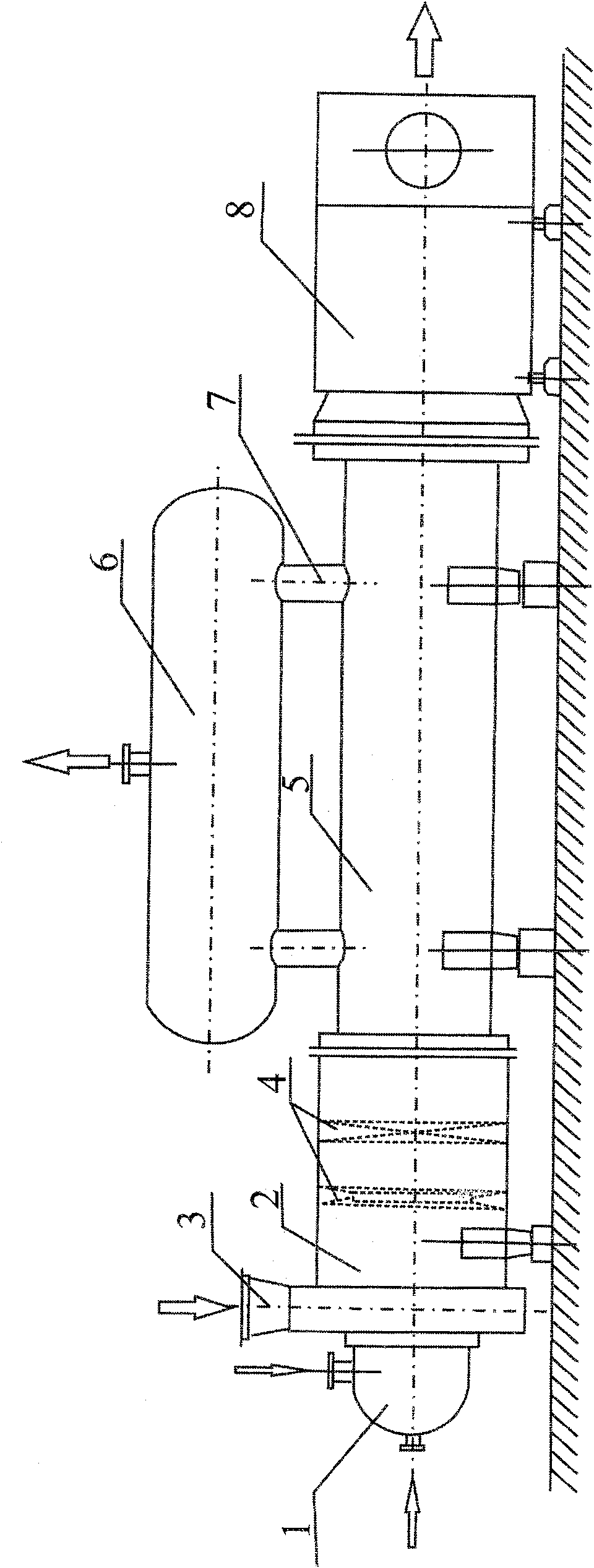
[0009] The present invention will be further described below in conjunction with the accompanying drawings.

[0010] Such as figure 1 As shown, the system includes a combustion chamber 1, a burning chamber 2, an annular chamber 3, a steam generator 6, and a water preheater 9 connected in series to form a serial system, wherein the combustion chamber 1 is connected with an air blower, and the combustion The chamber 1 and the burning chamber 2 are connected by the ring cavity 3, which is connected to the exhaust gas discharge pipe of the chemical plant, and the gas jet device is installed inside the ring cavity 3, so that multiple jets of the tail gas can enter the combustion chamber 1 and the burning chamber 3. It is fully mixed with air and burnt. A temperature uniform distribution device is installed in the burning chamber 2, which can accelerate the full combustion between air and exhaust gas and improve the mixing effect. The steam generator 5 is connected in series with t...


PUM


Abstract

The invention discloses a waste heat recovery system for the emptying tail gas treatment of a chemical device, which is characterized in that: the invention comprises a combustion chamber, a ring chamber, an ignition chamber, a steam generator and a water preheater orderly connected in series, wherein the ring chamber is connected with an emptying tail gas discharge pipeline for the chemical device, and the combustion chamber is connected with an air blower; the steam generator is provided with a steam drum, the steam drum is connected with the steam generator through one or over two sleeve pipe structures integrated with raising and declining by steam and water. The system has simple and reasonable structure and safe operation, saves energy sources, and realizes the purposes of the heat energy recovery of the chemical device and the reduction of tail gas discharge.

Description

technical field [0001] The invention relates to the technical field of tail gas treatment waste heat recovery, in particular to a waste heat recovery system for chemical plant venting tail gas treatment. Background technique [0002] In the prior art, the tail gas produced by some chemical plants (such as HCN plants) is directly discharged into the atmosphere, which not only pollutes the environment, but also causes energy waste. In response to this situation, some manufacturers have adopted exhaust gas treatment systems or waste heat recovery systems, but these systems have complex structures, cannot effectively recover energy and cause less environmental pollution, and have low operating efficiency, which poses safety hazards. Contents of the invention [0003] The technical problem to be solved by the present invention is how to provide a waste heat recovery system for exhaust gas treatment of chemical plants. The system has simple and reasonable structure, safe operati...

Claims


Application Information

Patent Timeline
Patent Type & Authority Patents(China)
IPC IPC(8): F23G7/06
CPCY02P20/10
Inventor 肖凤杳
Owner 曹乐季
Why Eureka
Try Eureka