Multi-path LED drive circuit

An LED drive and circuit technology, applied in the direction of electric lamp circuit layout, electric light source, lighting device, etc., can solve the problem of inability to accurately control the output current, and achieve the effect of saving power consumption, high current conversion efficiency, and large output resistance

Inactive Publication Date: 2010-01-20
SHENZHEN CHIP HOPE MICRO ELECTRONICS LTD
View PDF2 Cites 0 Cited by
  • Summary
  • Abstract
  • Description
  • Claims
  • Application Information

AI Technical Summary

Problems solved by technology

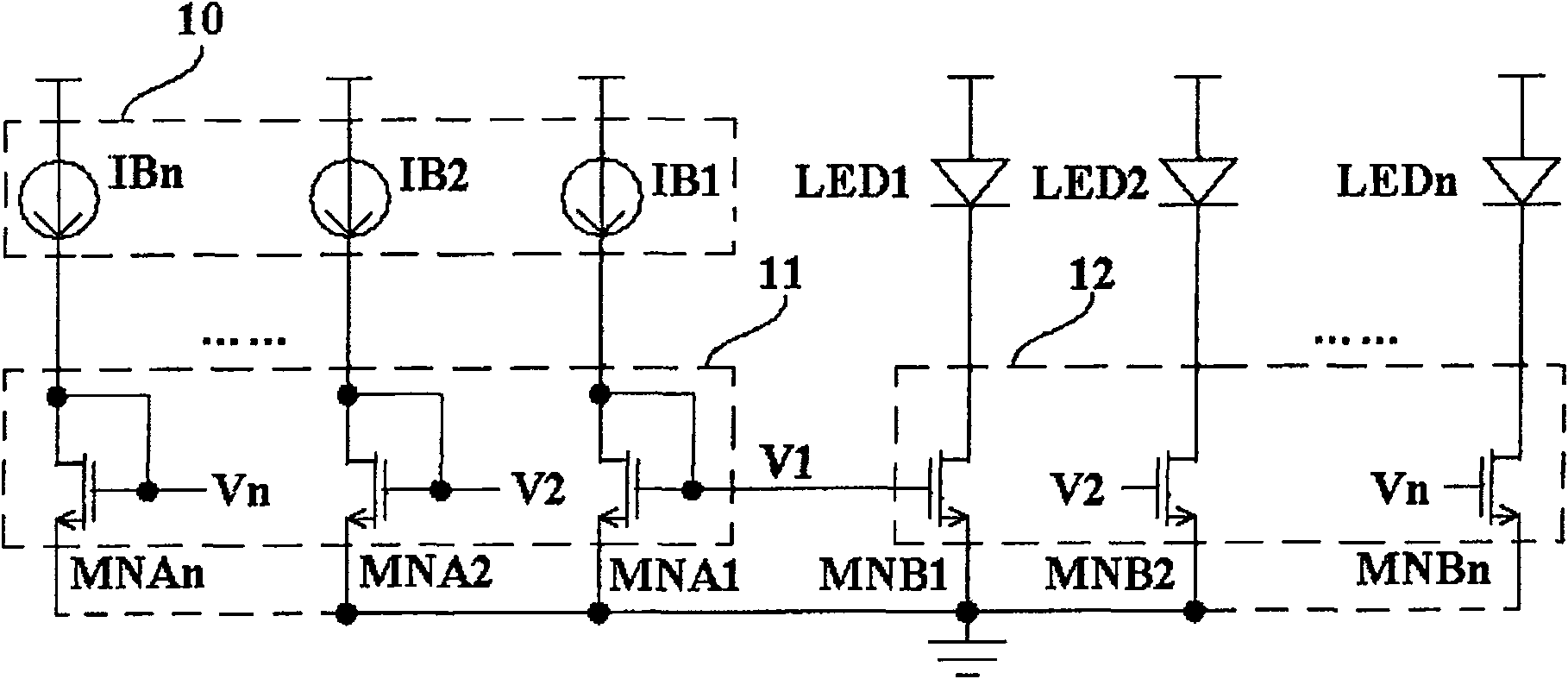
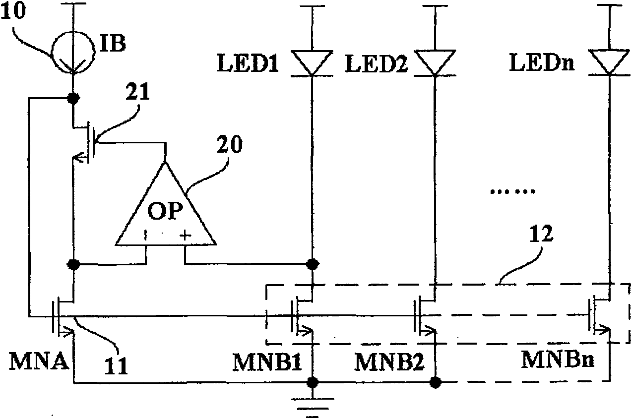
[0007] The technical problem to be solved by the present invention is that, aiming at the defect in the prior art that only detects the drain-source voltage signal of one of the driving tubes and cannot precisely regulate the output current of the other N-1 roads, it provides a A multi-channel LED drive circuit that detects the drain-source voltage signal and individually regulates the output current to achieve high-precision current matching

Method used


Image

  • Multi-path LED drive circuit
  • Multi-path LED drive circuit
  • Multi-path LED drive circuit

Examples


Embodiment Construction

[0022] image 3 It is a logic block diagram of the first embodiment of the multi-channel LED driving circuit of the present invention. It shows a multi-channel LED drive circuit, including a precise current source 30 for providing precise current, and a multi-channel mirror amplifier module 40 for amplifying and copying the precise current to multiple outputs, and also includes Active output stage 34 for precise regulation of each output.

[0023] Figure 4 It is the circuit diagram of the second embodiment of the multi-channel LED driving circuit of the present invention. Such as Figure 4 As shown, the current IB provided by the preset bias current source 10 reflects the magnitude of the output driving current, and the precision current source 30 accurately mirrors it to the output channel. The clamping effect of the first operational amplifier 31 makes the drain voltages of the first current mirror mirror transistor MP1 and the second current mirror mirror transistor MP...


PUM


Abstract

The invention relates to a multi-passage LED driving circuit, comprising an exact current source (30) which can provide exact current, a multi-passage mirror amplification module (40) which is used for amplifying the exact current and copies the amplified current to multi-passage output, and an active output-step (34) which can precisely regulate each passage of output. The embodiment of the multi-passage LED driving circuit can drive the multi-passage LED by one passage of prearranged bias current only, thus saving the power dissipation and having high current conversion efficiency; each passage of output current is independently detected and adjusted, the output current has high match precision, and the active output step structure has large output resistance and strong anti-interference capability.

Description

technical field [0001] The present invention relates to a driving circuit, more specifically, to a multi-channel LED driving circuit. Background technique [0002] The performance of light-emitting diodes (LEDs) in information display systems and backlight applications for portable devices is obvious to all. Today, when the voice of energy-saving and environmental protection technology is getting higher and higher, and LED lighting becomes the mainstream, LED driving technology is a topic that has attracted much attention and popularity. More and more forces are investing in the research of this technology, and the competition is becoming more and more fierce. [0003] Among them, the wide adoption of large-scale LED display screens requires the drive circuit to be able to drive a larger number of LEDs, which is often achieved by means of single-channel series connection, multi-channel parallel connection and inter-chip cascade connection. This kind of multi-channel LED dr...

Claims


Application Information

Patent Timeline
Patent Type & Authority Patents(China)
IPC IPC(8): H05B37/02
CPCY02B20/40
Inventor 周咏陈志军钟昌贤
Owner SHENZHEN CHIP HOPE MICRO ELECTRONICS LTD
Why Eureka
Try Eureka