Pipe type straight line permanent magnet synchronous motor

A permanent magnet synchronous motor technology, applied in the direction of electric components, electrical components, electromechanical devices, etc., can solve problems such as difficult cooling and heat dissipation, unilateral magnetic pull increases motor power loss, temperature rise, etc.

Inactive Publication Date: 2010-03-10
赵佰淼
View PDF5 Cites 0 Cited by
  • Summary
  • Abstract
  • Description
  • Claims
  • Application Information

AI Technical Summary

Problems solved by technology

[0003] The Chinese patent ZL200420018936.9 discloses a cylindrical permanent magnet linear synchronous motor. The secondary center of the road uses a stainless steel tube to isolate the magnetic field. The inner hole of the circular magnetic steel must pass through the stainless steel tube, and the inner hole of the magnetic steel should be larger than the diameter of the stainless steel tube. Unilateral magnetic pull increases motor power loss and reduces its thrust
This kind of linear synchronous motor uses roller bearings to adjust the air gap. There is a unilateral magnetic pull in the motor at any time. The unilateral magnetic pull will quickly cause the rollers to wear out and cause a lot of noise when the primary and secondary run over the groove.
The most difficult problem of the above-mentioned linear synchronous motor is that the temperature rise is too high during operation, which affects the life of the linear motor. It is difficult to solve the cooling and heat dissipation problem in the traditional way in the reciprocating motion

Method used


Image

  • Pipe type straight line permanent magnet synchronous motor

Examples


Embodiment Construction

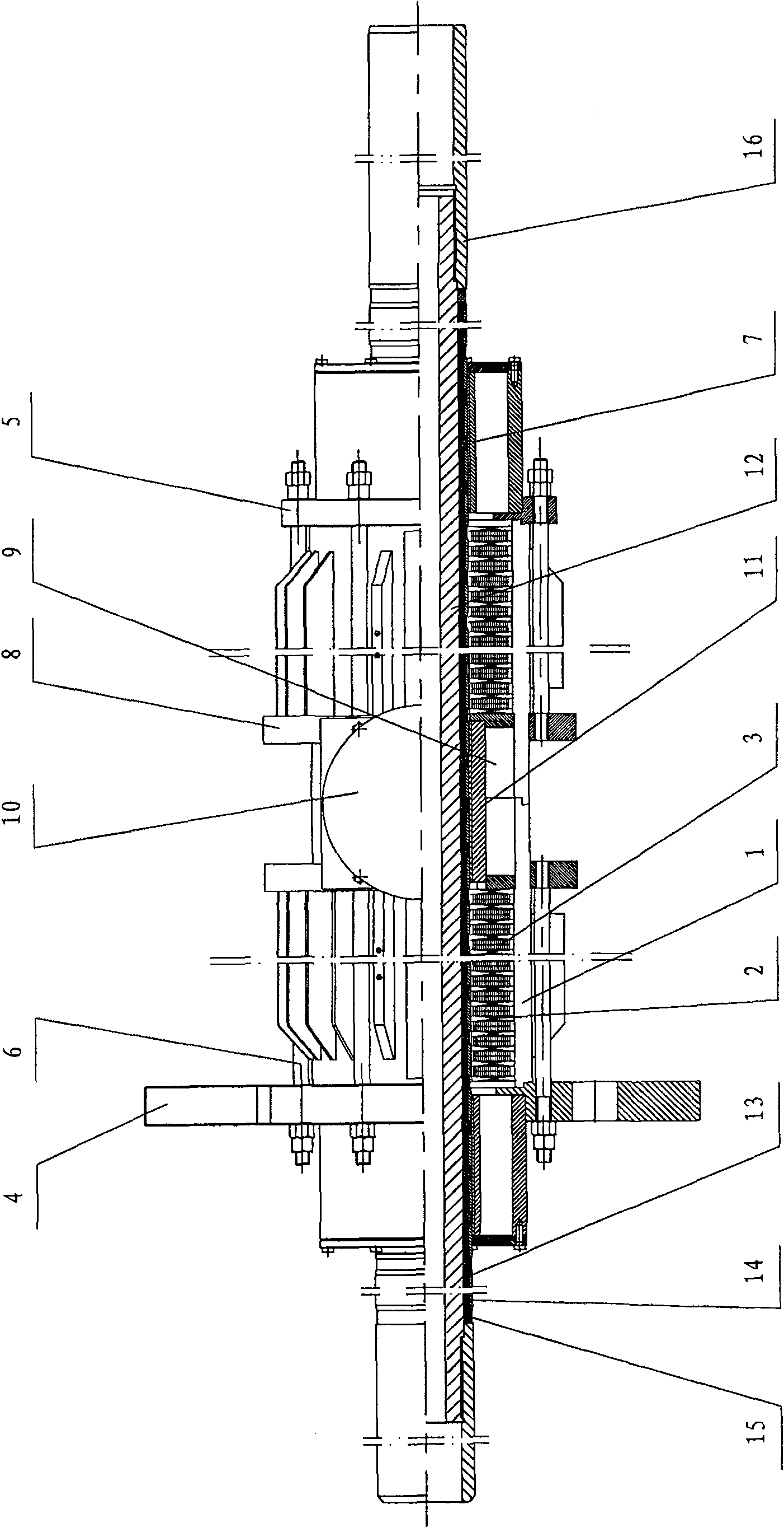
[0010] The present invention will be further introduced below in conjunction with the accompanying drawings: the present invention mainly includes primary and secondary poles. 3 are interlaced and installed in the casing, and are connected and press-fitted through the upper end cover 4, the lower end cover 5 and the screw rod 6 to form the primary part of the linear motor; It is made of resin casting; the upper end cover 4 and the lower end cover 5 are equipped with sliding bearings 7 and maintain the electromagnetic air gap between the primary poles. A fan 10 is installed symmetrically on the top of the blue, and a sliding bearing 11 is installed at the center in the middle of the casing.

[0011] In the present invention, a secondary steel pipe 12 is installed at the center of the primary part, and its outer wall is equidistantly inlaid with a plurality of tile magnets 13, and the tile magnets are covered with annular pole shoes 14, and the tile magnets 13 are radial For ma...


PUM


Abstract

The invention relates to a pipe type permanent magnet linear synchronous motor which consists essentially of a primary part and a secondary part, wherein, the primary part has the following structure:a pipe type integrated casing, a round iron core and two-row pie type windings are arranged; the round iron core and the two-row pie type windings are arranged in the casing in a staggered way, and connected with a screw rod by an upper end cover and a lower end cover and pressed to form the primary part of the linear synchronous motor; the upper end cover and the lower end cover are provided with sliding bearings internally and keep electromagnetic air-gap between primary and secondary electrodes; the middle part of the shell exterior is provided with symmetrical flange, the center of whichis provided with a ventilating duct and the upper part of which is provided with fans symmetrically arranged, and the center part in the middle of the casing is provided with a sliding bearing; a secondary steel pipe is positioned at the center part of the primary part, and the outer wall of the secondary steel pipe is embedded with a plurality of pieces of tile magnetic steel at equal intervals;the tile magnetic steel is sheathed with circular pole terminals and are magnetized in radial direction; one end of the magnetic steel is provided with a magnetic-separating ring which is made from non-magnetic material; and two ends of the secondary steel pipe are provided with upper and lower connecting pipes and combined into the secondary with magnetization in radial direction. The linear synchronous motor of the invention has the advantages of reasonable, novel and compact structure with small volume, large pushing force and stable operation without noise.

Description

technical field [0001] The invention relates to a tubular linear permanent magnet synchronous motor, which belongs to the technical field of motors. technical background [0002] Linear motor is a power device that directly converts electrical energy into linear motion without intermediate mechanical conversion. It is prominently used in transmission devices that require linear motion, such as pumping units in oil field oil production equipment, three-dimensional garages, and mine resource transmission. The advantages are new products with new principles, new theories, and new technologies emerging in the electrical field. [0003] Chinese patent ZL200420018936.9 discloses a cylindrical permanent magnet linear synchronous motor. The secondary center of the road uses a stainless steel tube to isolate the magnetic field. The inner hole of the circular magnetic steel must pass through the stainless steel tube, and the inner hole of the magnetic steel should be larger than the ...

Claims


Application Information

Patent Timeline
Patent Type & Authority Patents(China)
IPC IPC(8): H02K41/03
Inventor 赵佰淼
Owner 赵佰淼
Why Eureka
Try Eureka