Mechanization production line of cement sand wich light wall board

A light-weight partition board and production line technology, applied in the direction of ceramic forming machines, forming conveyors, manufacturing tools, etc., can solve the problems of low production efficiency, complicated operation, high labor intensity, etc., and achieve high production efficiency and stable product quality Effect

Inactive Publication Date: 2007-07-18
SHANDONG UNIV
0 Cites 20 Cited by

AI-Extracted Technical Summary

Problems solved by technology

[0003] At present, the production of lightweight partition boards with cement sandwich is mainly separated by manual processes. Mold molding, complex operation, high labor intensity, low production efficiency, product quality is often not guaranteed, and it is difficult to form a scale
Although semi-mechanical production processes and equipment such as spiral extrusion molding...

Abstract

The present invention provides a mechanization production line of cement sandwich light partition wall panel. Said production line includes mould box continuous operation equipment and successively-arranged manipulator for laying base net, pouring machine for pouring base layer slurry material, manipulator for laying core plate, pouring machine for pouring four-side and top layer slurry material, manipulator for screeding slurry, manipulator for laying upper-layer net, press roll for press-finishing slurry, manipulator for demoulding and manipulator for conveying finished product.

Application Domain

Ceramic shaping plantsPress rollers +1

Technology Topic

Image

  • Mechanization production line of cement sand wich light wall board

Examples

  • Experimental program(1)

Example Embodiment

[0012] Example
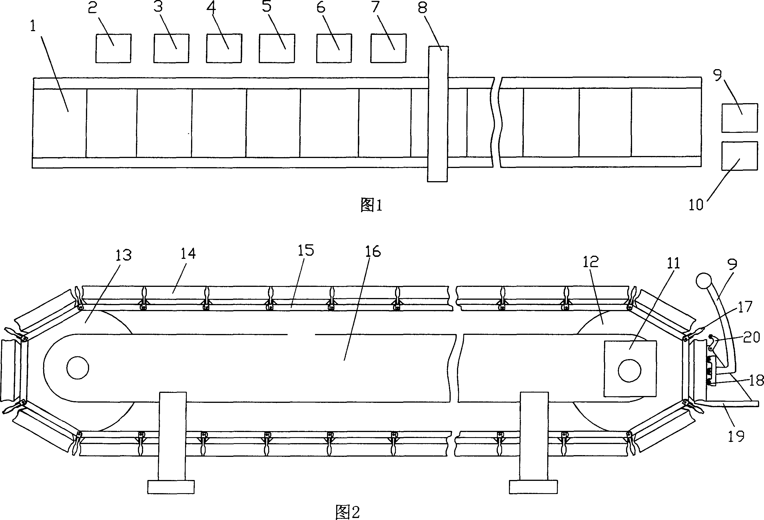
[0013] As shown in Figure 1, the production line of the present invention includes a mold box continuous operation device 1 and arranged in order: a manipulator for laying the bottom net 2, a pouring machine 3 for pouring the bottom slurry, a core board for laying Manipulator 4, pouring machine for pouring the surrounding and upper layer slurry 5, manipulator used for leveling the slurry 6, manipulator used for laying the upper layer net 7, pressure roller used for slurry calendering 8, used for demolding The demolding robot 9 and the transfer robot 10 for handling finished products. The manipulator adopts the current general products, and controls each manipulator to coordinate and complete its functions through the control program.
[0014] The structure of the mold box continuous operation device 1 is shown in Figure 2, including a frame 16, a power transmission device 11, a driving sprocket 12, a passive sprocket 13 and a mold box 14. The power transmission device 11 and the passive sprocket 4 are respectively installed on At both ends of the frame 16, the driving sprocket 12 is installed on the output shaft of the power transmission device 11. A chain 15 is installed between the driving sprocket 12 and the passive sprocket 13, and a group of multiple horizontally arranged together is installed on the chain 15的模箱14。 The mold box 14. Each mold box circulates with the rotation of the chain. The power transmission device 11 may adopt a geared motor. The size and shape of the mold box 14 are customized according to the size and shape of the cement sandwich light partition wall panel to be manufactured. The two ends of the mold box 14 are provided with mold box wall panels 17 installed on chains.
[0015] The frame 16 is also connected with a finished product rack 19 for placing finished products, and the finished product rack 19 is provided with an anti-dropping block 20 to prevent the finished product from slipping. When the mold box with the finished product moves downwards, the roller 18 on the demolding robot 9 presses on the finished product in the mold box 14, so that the finished product is smoothly demolded and placed on the finished product rack 19, and then transported away by the transfer robot 10 .
[0016] The working process of the present invention is:
[0017] The mold box 14 is fixed on the chain 15 and moves at a constant speed under the drive of the sprocket. The following processes are completed during the movement:
[0018] In the first step, the bottom netting robot 2 unfolds the bottom net cloth, cuts it off according to size, and lays it on the bottom plate of the mold box 14;
[0019] In the second step, the bottom layer slurry is poured through the grouting machine 3;
[0020] The third step is to lay the core board manipulator 4 to flatten the prepared sandwich board onto the bottom slurry;
[0021] In the fourth step, the surrounding and upper layer slurry is poured by the grouting machine 5, and the slurry is scraped by the slurry leveling manipulator 6 to level the slurry with a scraper;
[0022] The fifth step is to lay the upper mesh manipulator 7 to unfold the mesh cloth, cut it according to the size, and lay it on the slurry and press it into a certain depth;
[0023] The sixth step is to calender the slurry through the pressing roller 8 and apply a light film; then enter the solidification zone, and the solidification time (determined by the chain operation period) is related to the additives and the properties of the raw materials;
[0024] In the seventh step, after solidifying to a certain degree, the mold box wall panel 17 is turned obliquely downward due to the action of the sprocket. At this time, the two sides of the mold box wall panel 17 and the end of the mold box are automatically peeled off, and the finished product frame 19 The anti-dropping block 20 prevents the finished product from slipping. When the mold box wall plate 17 moves to the near vertical position, the demolding manipulator 9 is in place, so that the finished product is smoothly demolded and placed on the finished product rack 19, and then transported by the transfer manipulator 10.
[0025] The above-mentioned processes operate continuously to realize mechanized production.

PUM

no PUM

Description & Claims & Application Information

We can also present the details of the Description, Claims and Application information to help users get a comprehensive understanding of the technical details of the patent, such as background art, summary of invention, brief description of drawings, description of embodiments, and other original content. On the other hand, users can also determine the specific scope of protection of the technology through the list of claims; as well as understand the changes in the life cycle of the technology with the presentation of the patent timeline. Login to view more.

Similar technology patents

Method for Producing L-Amino Acids Using Bacteria of the Enterobacteriaceae Family

ActiveUS20060141586A1Increase productivityBacteriaHydrolasesEnterobacteriaceae bacteriumL-Arabinose
Owner:AJINOMOTO CO INC

Classification and recommendation of technical efficacy words

  • Increase productivity
  • Product quality is stable

Apparati, methods, and compositions for universal microbial diagnosis, detection, quantification, and specimen-targeted therapy

InactiveUS20120129794A1Increase productivityAccurate and rapid and sensitive microbial diagnosis and detection and quantificationAntibacterial agentsBiocidePopulationMolecular Targeted Therapies
Owner:DOWD SCOT E +2

People also interested in

Why Eureka
Try Eureka