Roof windpower generating apparatus

A wind power generation device and wind power technology, applied in wind turbine components, electromechanical devices, wind power generation and other directions, can solve problems such as power loss, and achieve the effect of shortening transmission lines, reducing power loss, and reliable overload protection capability.

Inactive Publication Date: 2007-07-18
NORTHEAST DIANLI UNIVERSITY
View PDF0 Cites 15 Cited by
  • Summary
  • Abstract
  • Description
  • Claims
  • Application Information

AI Technical Summary

Problems solved by technology

[0005] 3) The local power grid must generate a certain amount of power loss, which accounts for about 6-10% of the wind farm's power generation

Method used


Image

  • Roof windpower generating apparatus
  • Roof windpower generating apparatus
  • Roof windpower generating apparatus

Examples


Embodiment

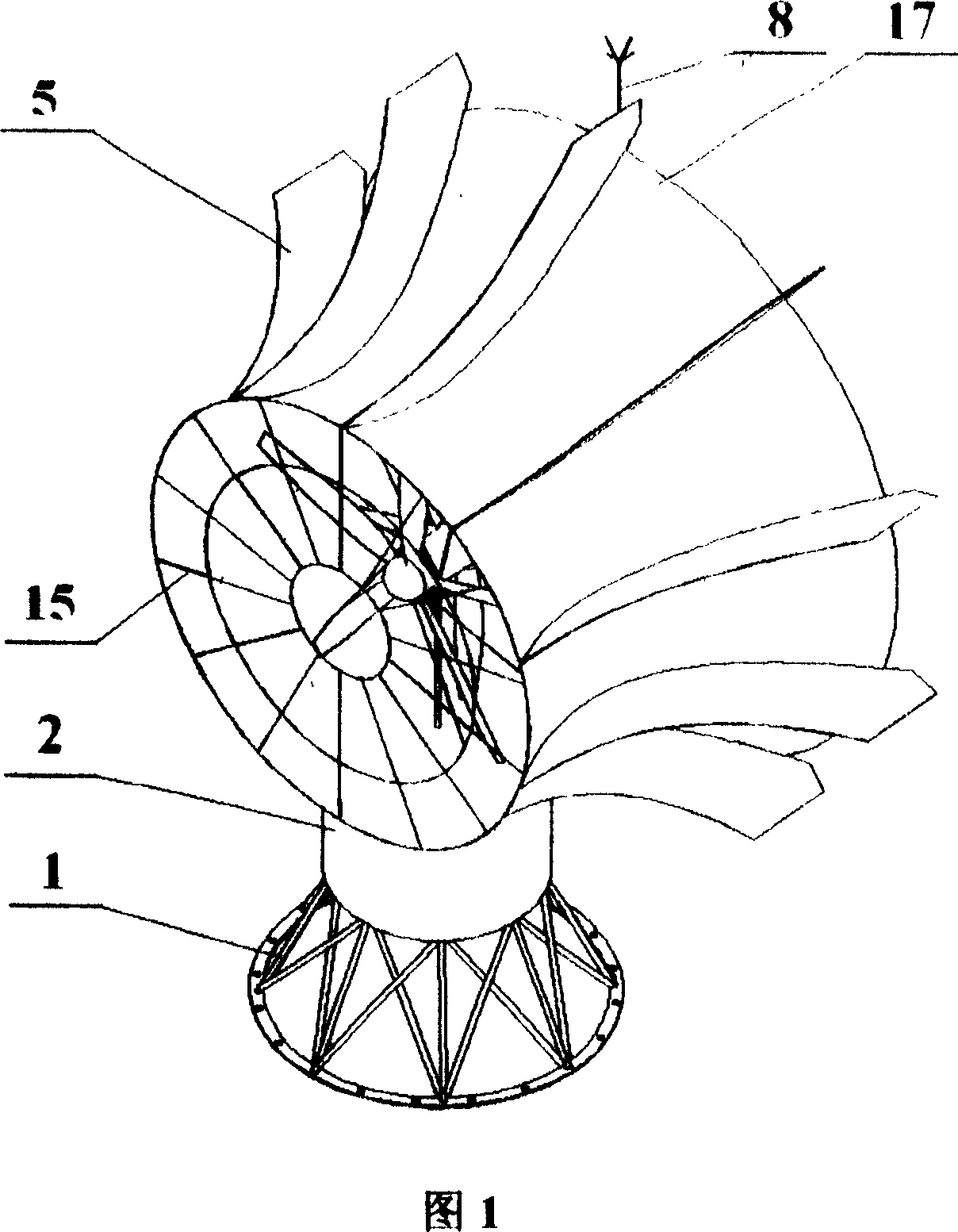
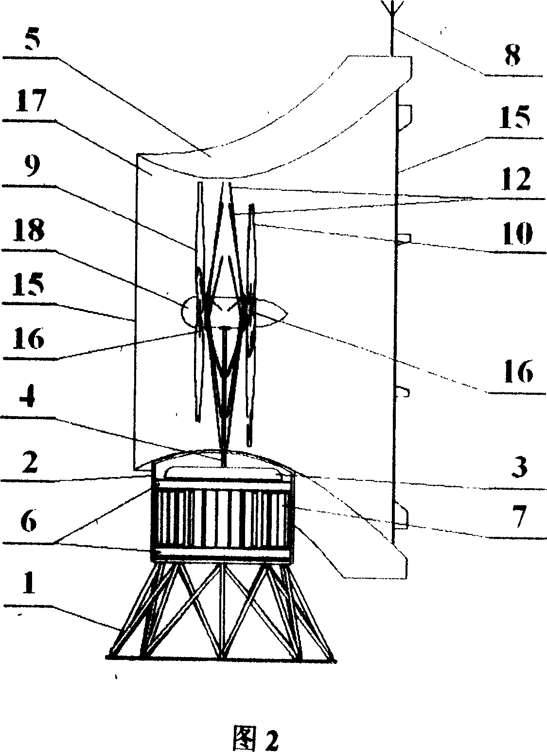
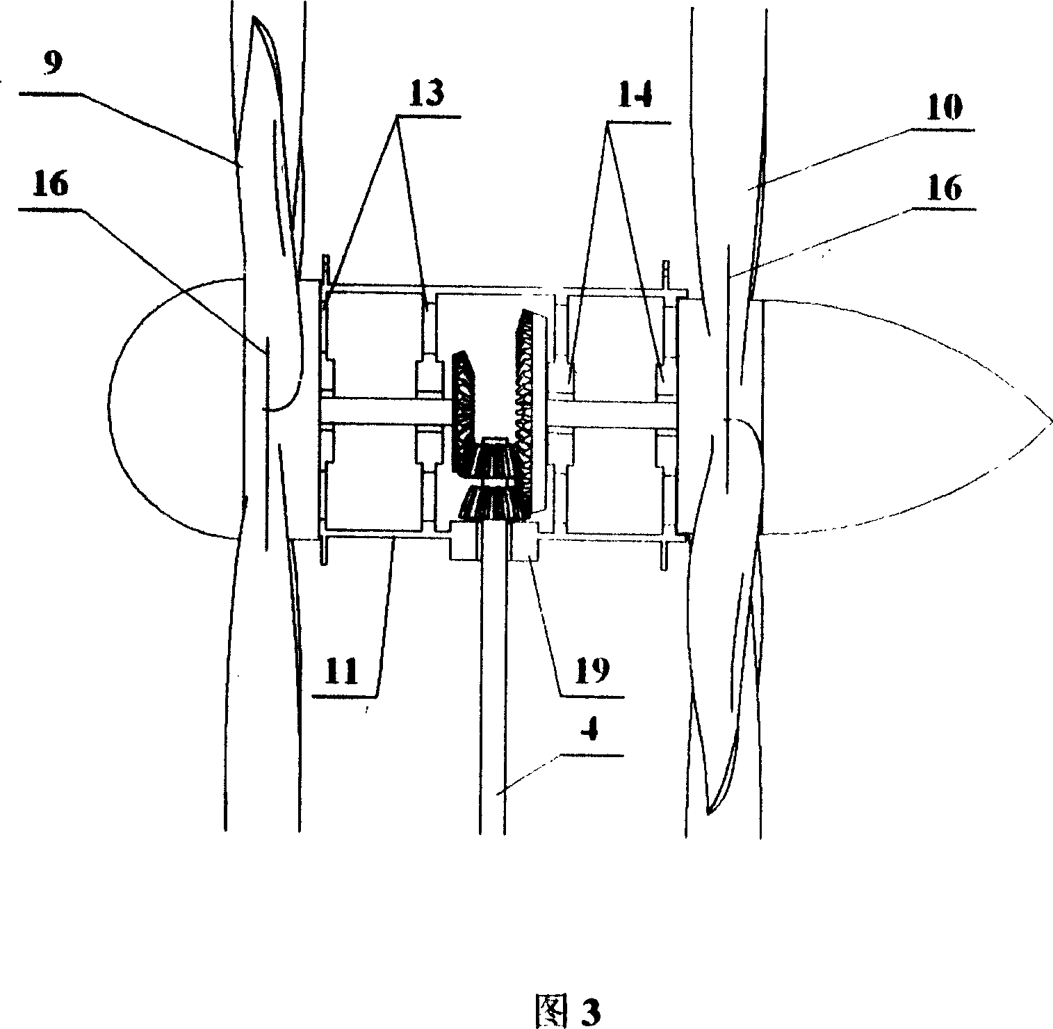
[0031] It can be seen from Fig. 1 to Fig. 3 that a roof wind power generation device according to the present invention mainly includes a tower 1, a wind turbine 18, a generator 3, a steering acceleration shield 17 and the like. The tower 1 is a short tower with a height of 1.5-2.5m (it can be made of steel or aluminum alloy, etc.), and it is installed and rooted on the beam or floor of the building roof. The diameter of the wind turbine 18 is no more than 3m; a generator 3 is fixed on the top of the short tower. Between the generator 3 and the generator compartment 2, two sets of steering bearings 6 are used to connect, and between the two sets of steering bearings are generator cooling fins 7; 17 is fixedly connected as a whole; The direction-tuning acceleration protection wind machine cover 17 has directional wing 5, and its housing is provided with air inlet, air outlet; And its outer surface is equipped with a rudder, so that the air inlet is always facing the direction ...


PUM


Abstract

The roof wind driven generator set includes a wind mill of diameter smaller than 3 m, a short tower rooted on the roof beam, a generator fixed to the top of the short tower and connected to the generator room through bearings with heat sink, a housing of asymmetrical structure, an orientating wing in the outer surface of the housing for the wind inlet always in the wind direction, a lightning arrester and other parts. The generator is connected electrically to the power supply of the building and may provided with an incorporating regulator for incorporating to power network.

Description

technical field [0001] The invention belongs to a wind power generation device, in particular to a roof wind power generation device. Background technique [0002] The development direction of modern wind power generation technology is to use wind power generation device groups to build large-scale wind farms and connect them to the grid for power generation. At present, there are mainly the following problems in modern wind power generation technology that need to be solved or improved: [0003] 1) In order to capture high-altitude wind energy, a steel tower of 30 to 120 meters must be built, and the wind turbine is installed on the upper end of the steel tower. The investment in steel towers accounts for about 30% of the total investment. If the height of the steel tower can be reduced more, the investment of the whole wind power generation device will be obviously reduced. [0004] 2) It is necessary to build a local power network to realize the connection between each...

Claims


Application Information

Patent Timeline
Patent Type & Authority Applications(China)
IPC IPC(8): F03D9/00F03D11/04F03D1/06F03D1/04H02K7/18F03D9/25F03D9/45F03D13/20
CPCY02E10/725Y02E10/728Y02E10/721Y02B10/30Y02E10/72
Inventor 张炳文周云龙吕太张莹瑾周爽吕勇兴
Owner NORTHEAST DIANLI UNIVERSITY
Why Eureka
Try Eureka