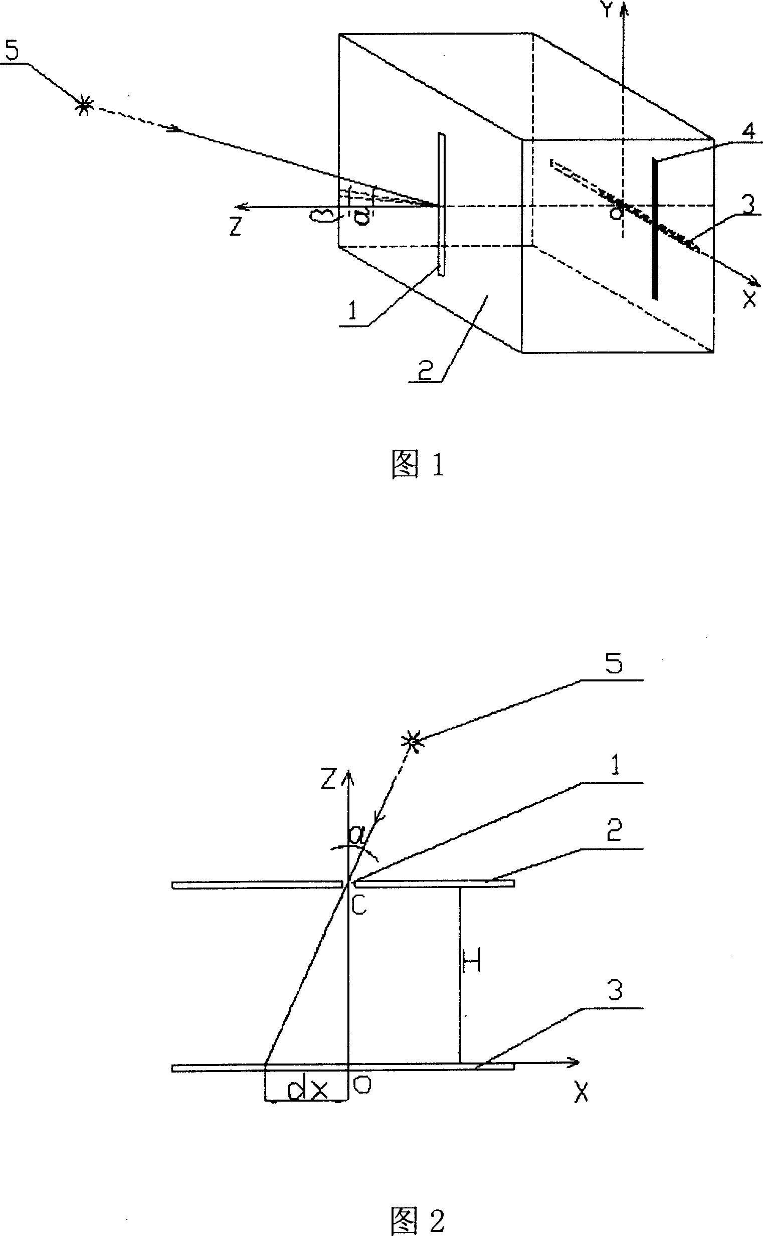
Angle measuring probe for motion optical target
A target and motion technology, applied in the field of angle measuring probes, can solve problems such as complex application, complex equipment, and long cycle, and achieve the effects of small size, short manufacturing cycle, and convenient operation
Inactive Publication Date: 2007-07-18
CHANGCHUN INST OF OPTICS FINE MECHANICS & PHYSICS CHINESE ACAD OF SCI
View PDF0 Cites 6 Cited by
- Summary
- Abstract
- Description
- Claims
- Application Information
AI Technical Summary
Problems solved by technology
These devices are very complex, with long development and production cycles, high costs, and complex applications.
Method used
View moreImage
Smart ImageViewing Examples
Examples
Embodiment Construction
[0018] The present invention is implemented by the structure shown in FIG. 1 . The hood 2 is a closed hollow regular hexahedron with a side length of 8cm, cast aluminum material with a thickness of 3mm, and the inner wall surface is painted black. The size of the light-transmitting slit 1 is 15mm high and 0.1mm wide. The linear array CCD3 adopts TCD1500C.
Login to View More PUM
 Abstract
The invention relates to movable light target angular measure probe. Its technology scheme is as follows: it includes photic slit, lens hood, linear CCD, slit projecting light; the lens hood is closed hollow hexahedron on which rectangular coordinate system is set; one side wall center is coordinate origin 'O'; upright center line is OY axes; level center line is OX axes; the connecting line between the 'O' point and the corresponding side wall center is OZ axes; linear CCD is set at the side wall level center line; and its midpoint is coincided with the coordinate origin 'O'; another side wall upright center line is set photic slit of which center the OZ axes is passed through. The slit projecting light is fallen on the side wall inner and normal to the linear CCD. The photic slit faces to movable light target while using.
Description
1. Technical field [0001] The invention belongs to an angle measuring probe related to the technical field of photoelectric measurement. 2. Technical background [0002] The so-called moving light target means that the position of the light target in space will change as time goes by. For observers, it is necessary to produce an angle change with the observation position, such as the sun, which is a huge moving light source, with sunrise in the east and sunset in the west every day. For observers, the space azimuth and elevation angle of the sun are changing at any time. Measuring the instantaneous angle change with the sun is very meaningful for industrial and agricultural production, scientific research, and utilization of solar energy. For another example, jet engine flame vents and rocket engine flame vents can be regarded as moving light targets in the air, and as time goes by, they also have angle changes relative to the observer. Measuring the instantaneous angle c...
Claims
Login to View More Application Information
Patent Timeline
 Patent Type & Authority Applications(China)
IPC IPC(8): G01C1/00
Inventor 王显军张亚轩
Owner CHANGCHUN INST OF OPTICS FINE MECHANICS & PHYSICS CHINESE ACAD OF SCI
Features
- R&D
- Intellectual Property
- Life Sciences
- Materials
- Tech Scout
- Unparalleled Data Quality
- Higher Quality Content
- 60% Fewer Hallucinations
Learn More Browse by: Latest US Patents, China's latest patents, Technical Efficacy Thesaurus, Application Domain, Technology Topic, Popular Technical Reports.
© 2025 PatSnap. All rights reserved.Legal|Privacy policy|Modern Slavery Act Transparency Statement|Sitemap|About US| Contact US: help@patsnap.com

