Method for implementing train positioning and real-time tracking using coherence optical fibre raster set

A fiber grating and real-time tracking technology, which is applied in the direction of using optical devices to transmit sensing components, signal transmission systems, instruments, etc., to achieve the effect of shortening the distance between vehicles

Inactive Publication Date: 2007-07-18
BEIJING JIAOTONG UNIV
View PDF0 Cites 22 Cited by
  • Summary
  • Abstract
  • Description
  • Claims
  • Application Information

AI Technical Summary

Problems solved by technology

However, the method of using fiber gratings to realize train positioning and re

Method used


Image

  • Method for implementing train positioning and real-time tracking using coherence optical fibre raster set
  • Method for implementing train positioning and real-time tracking using coherence optical fibre raster set

Examples


Embodiment 1

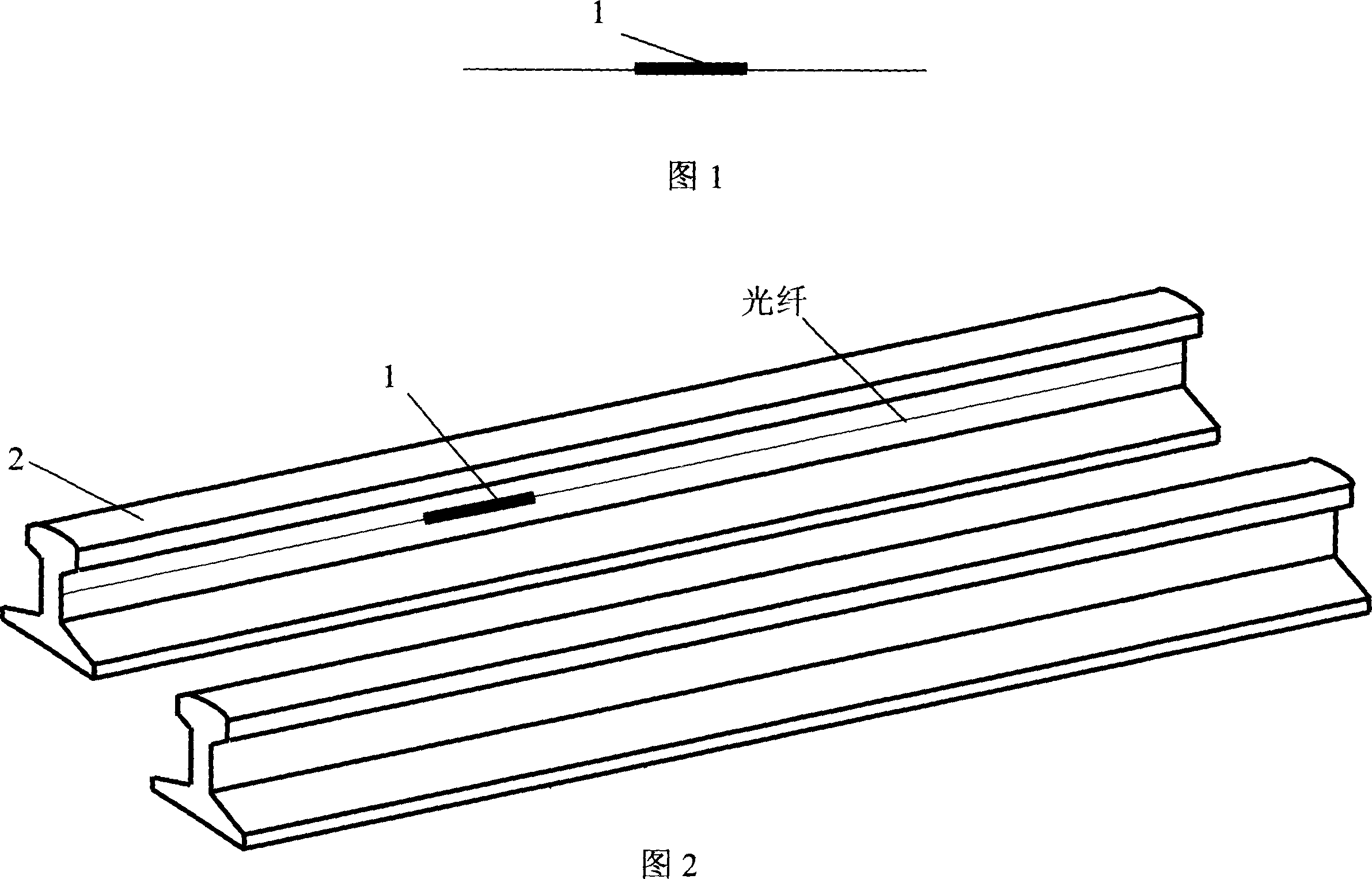
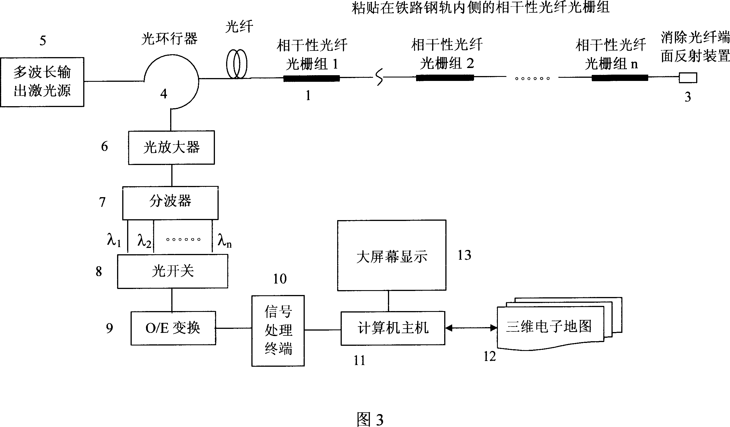
[0012] Embodiment 1: as shown in Figures 1, 2, and 3, the present invention has adopted n coherent fiber grating groups (1) of wavelength division multiplexing, and n coherent fiber gratings of wavelength division multiplexing are used in the whole course of rail transit The group is close to the inner side of the rail (2), and the end of the fiber grating group is connected to eliminate the reflection of the fiber end face (3). This fiber grating group has a resin protective layer, one end of the optical fiber is connected to the multi-wavelength laser transmitter (5) of the traffic command center through the circulator (4), and the other end of the circulator is connected to the wave splitter after the optical amplifier (6) (7).

[0013] When the locomotive travels to the sensitive area of ​​the i-th coherent fiber grating group, the amplitude oscillation of the corresponding wavelength will be generated. When the locomotive reaches the center of the assembly, the amplitude...

Embodiment 2

[0018] Embodiment 2: The present invention adopts wavelength division multiplexing n coherent fiber grating groups with resin protection layer to be close to the inner side of the rail during the whole rail transit. The distance between fiber grating groups is about 200-300 meters, which is equivalent to shortening the blocking interval of general track circuits by 10 times. When the locomotive travels to the sensitive area of ​​the i-th coherent fiber grating group, the amplitude oscillation of the corresponding wavelength will be generated. When the locomotive reaches the center of the assembly, the amplitude of the oscillation at this wavelength reaches its highest point. As the locomotive moves away from the center position, the oscillation amplitude will decrease accordingly. One end of the optical fiber is connected to the multi-wavelength laser transmitter of the traffic command center through a circulator, the other end of the circulator is connected to a fiber amplif...


PUM


Abstract

The invention relates to a method used coherence optical fiber grating set to realize train positioning and real time tracking. It includes the following steps: using wavelength division multiplex n coherence optical fiber grating sets with resin protective layer to cling to the rail inside; the interval of the optical fiber grating is about 200-300m which shortens common track circuit blocking area by ten times; when locomotive drives to the its coherence optical fiber grating set sensitive area, it will produce amplitude vibration with corresponding wave; one end of the optical fiber is connected multiple wavelength laser launcher in the control center by circulator of which another end is connected with fiber amplifier, then connected with the wave separator of which separated wavelength is transformed into electric signal; all electric signal are input into the digital signal processing terminal to exactly figure out train exact position, speed, and acceleration to realize exact positioning and real time tracking.

Description

technical field [0001] The "method for realizing train positioning and real-time tracking by using coherent fiber grating groups" of the present invention belongs to the technical field of rail transit vehicle-ground communication and train real-time tracking, and is especially suitable for high-speed railway vehicle-ground communication and train real-time tracking technical fields. Background technique [0002] Fiber Bragg gratings have been widely used in optical fiber sensing technologies such as temperature, pressure, and tension. However, there is no relevant report on the method of using fiber grating to realize train positioning and real-time tracking by coherent fiber grating group. Contents of the invention [0003] In order to overcome the deficiencies of the prior art, the invention provides a method for realizing train positioning and real-time tracking by using a coherent fiber grating group. [0004] The technical scheme adopted by the present invention to ...

Claims


Application Information

Patent Timeline
IPC IPC(8): G01D5/353B61L25/02G08C17/02G08C19/00
Inventor 简水生延凤平谭中伟任文华郑晶晶
Owner BEIJING JIAOTONG UNIV
Why Eureka
Try Eureka