
Flat panel display and display device

A flat-panel display and display device technology, applied in identification devices, static indicators, AC plasma display panels, etc., can solve problems such as increased power consumption, easy fluctuations, and increased parasitic capacitance, so as to reduce power consumption and discharge delay , Excellent productivity

Inactive Publication Date: 2007-07-18
FUJITSU HITACHI PLASMA DISPLAY LTD
View PDF2 Cites 0 Cited by
  • Summary
  • Abstract
  • Description
  • Claims
  • Application Information

AI Technical Summary

Problems solved by technology

[0010] (2) The film quality (crystal orientation) that determines the ferroelectric properties tends to fluctuate
[0011] (3) If a ferroelectric material is used as a layer, the parasitic capacitance increases and the power consumption increases

Method used


Image

  • Flat panel display and display device
  • Flat panel display and display device
  • Flat panel display and display device

Examples


Embodiment Construction

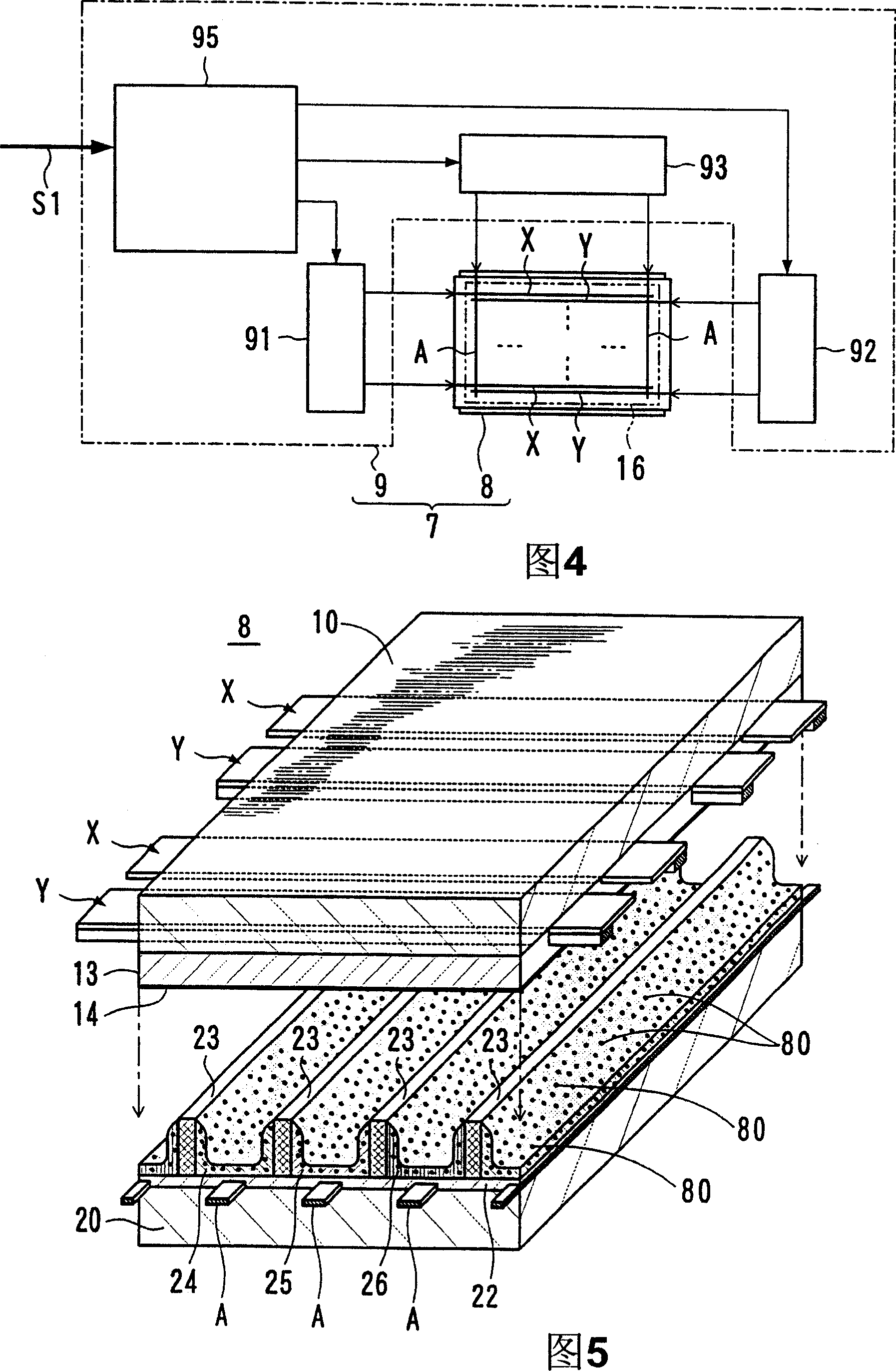
[0049] FIG. 4 shows the configuration of the display device of the present invention.

[0050] The display device 7 is composed of a three-electrode surface discharge AC type plasma display panel 8 capable of displaying a color screen 16 , and a drive circuit 9 for driving the plasma display panel 8 .

[0051] On the screen 16 of the plasma display panel 2 , first display electrodes X and second display electrodes Y as row electrodes are alternately arranged, and address electrodes A as column electrodes are arranged alternately. On each row of the screen 16, the display electrode X and the display electrode Y form an electrode pair for generating sustain discharge in the form of surface discharge. The address electrode A intersects the display electrode X and the display electrode Y in each cell belonging to the column where it is arranged. In addition, the display electrode X and the display electrode Y are respectively composed of a thick strip-shaped transparent conductiv...


PUM


Abstract

A flat panel display includes a discharge space filled with discharge gas and a plurality of electrodes for generating discharge in the discharge space. Ferroelectric powder is disposed between the electrodes and the discharge space so that the ferroelectric powder contacts the discharge space.

Description

technical field [0001] The present invention relates to a flat panel display for display by gas discharge called a plasma display panel (PDP) and a plasma address liquid crystal (PALC) and a display device having such a flat panel display. Background technique [0002] A display device having an AC type plasma display panel performs a data write operation called addressing to set on / off lighting of cells constituting a screen, and continues a display operation called sustain after addressing. In addition, in general, a so-called initialization operation is performed first in addressing. The purpose of performing the initialization operation is to make the charge storage state of the cells uniform and to generate trigger particles that easily cause discharge during addressing (address discharge). [0003] However, the trigger particles decrease with time from the initialization action, and the discharge delay increases accordingly. Discharge delay can generally be considere...

Claims


Application Information

Patent Timeline
Patent Type & Authority Applications(China)
IPC IPC(8): H01J17/49H01J17/02H01J17/04H01J11/00H01J11/02G09F9/313G09G3/28H01J11/12H01J11/22H01J11/24H01J11/26H01J11/34H01J11/36H01J11/38H01J11/40H01J11/42H01J11/50
CPCG09G3/293H01J11/12H01J11/42H01J11/38H01B3/00H01B3/12
Inventor 福田晋也瀬尾欣穗别井圭一
Owner FUJITSU HITACHI PLASMA DISPLAY LTD
Learn More