Brushless synchronous communicating DC hub motor

A technology of in-wheel motors and commutators, applied in the direction of motors, DC commutators, circuits, etc., can solve the problems of inability to directly apply the electric system of electric vehicles, impracticability, and reduced efficiency, and achieve small sparks, high motor efficiency, and The effect of low friction

Inactive Publication Date: 2007-07-18
杨光笋 +2
View PDF0 Cites 5 Cited by
  • Summary
  • Abstract
  • Description
  • Claims
  • Application Information

AI Technical Summary

Problems solved by technology

[0002] The existing brushed motor operation mode is that the housing is fixed and the main shaft rotates, which cannot be directly applied to electric vehicles and other electric systems that are not suitable for this operation mode
Although the current silicon-controlled brushless motor solves this problem, it is only limited to low-speed operation. The defect is that if it is operated at high speed, the no-load current will increase with the increase of voltage, and increase with the increase of speed, and the efficiency will also decrease. accomplish

Method used


Image

  • Brushless synchronous communicating DC hub motor
  • Brushless synchronous communicating DC hub motor
  • Brushless synchronous communicating DC hub motor

Examples


Embodiment Construction

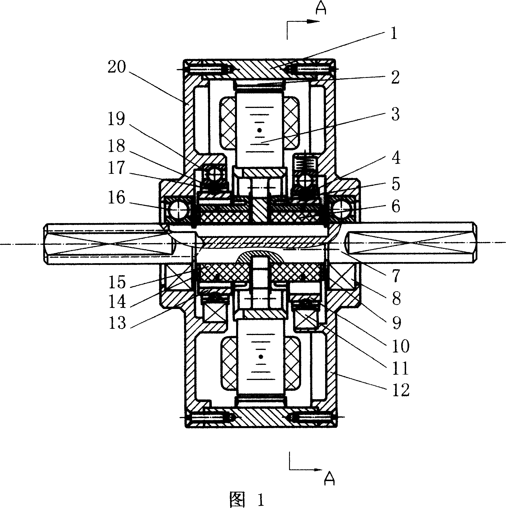
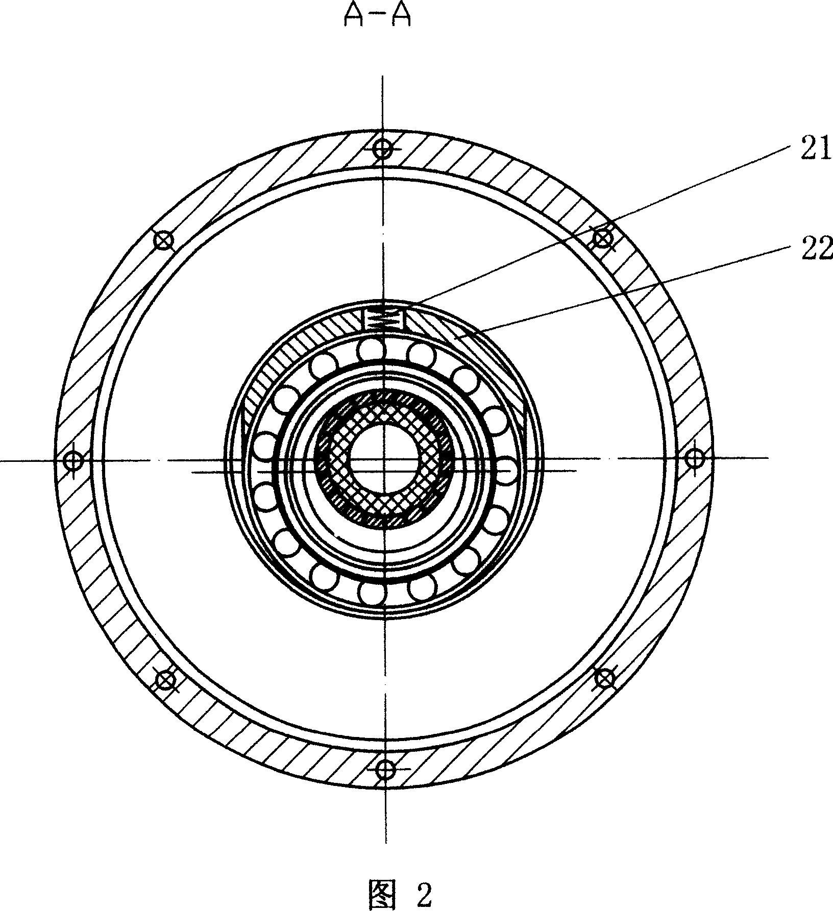
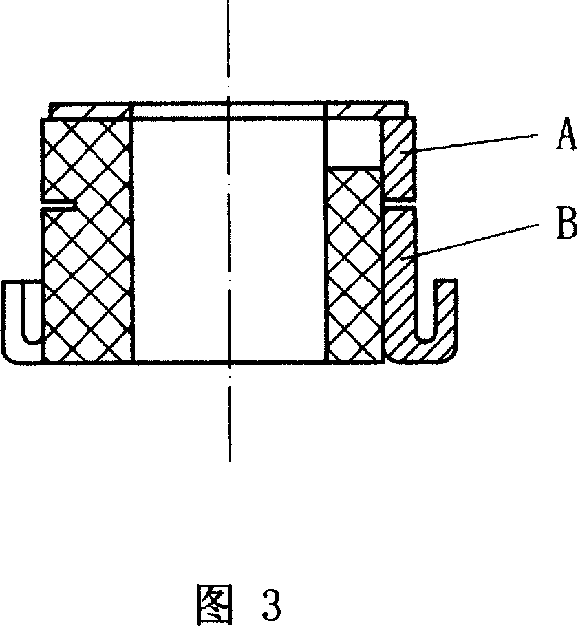
[0032] Referring to Figures 1, 2, and 3, a brushless synchronously commutated DC hub motor includes a main shaft 7, a rotor 2, a stator 3, a left synchronous ring 13, a right synchronous ring 10, a left commutator 15 and a right commutator 6 . The stator 3 is located in the middle of the housing 1 and is fixed on the main shaft 7, and a left commutator 15 and a right commutator 6 are arranged on both sides. The commutator is composed of a power supply ring A and a commutator piece B. The left commutator 15 is tangent to the left synchronous ring 13 through the left synchronous spring and the left synchronous balance weight. Tangent to the right synchronous ring 10. The left insulating ring 18 is sleeved on the inner bearing 19 of the left end cover, the left synchronous ring 13 is rollingly fitted with the left commutator 15, and a left flexible universal ring 17 is arranged between the left insulating ring 18 and the left synchronous ring 13; the right insulating ring 4 is ...


PUM


Abstract

This invention relates to a brushless synchronous commutating DC hub motor driven by power used in electromotive cars, in which, a stator is placed at the middle of the shell and fixed on the main shaft with commutators at both sides composed of a supply ring and commutating plates tangent to synchronous rings inside or outside jacketed on bearings in right and left covers of the shell by a flexible universal ring, the rotor is fixed in the shell composing an output structure with it, a lead enters via a main shaft hole and is connected with a supply touch plate to constitute a supply input structure, and the leads at both ends, the supply touch plates, a supply ring, a synchronous ring, commutating plates and the stator winding coil make up of a closed circuit, when it is turned on, it generates electromagnetic induction to push the rotor to drive the synchronous rings to move periodically along the commutator to turn current to commutate and drive the rotor rotating in the same direction.

Description

technical field [0001] A brushless synchronously commutated DC in-wheel motor related to electric drive for electric vehicles. Background technique [0002] The existing brushed motor operates in a fixed housing and rotates the main shaft, which cannot be directly applied to electric vehicles and other electric systems that are not suitable for this operation mode. Although the current silicon-controlled brushless motor solves this problem, it is only limited to low-speed operation. The defect is that if it is operated at high speed, the no-load current will increase with the increase of voltage, and increase with the increase of speed, and the efficiency will also decrease. accomplish. Contents of the invention [0003] In order to overcome the above-mentioned defects of the prior art, the present invention provides a brushless synchronous commutation DC wheel hub motor. This device is not limited by the rotational speed while realizing the rotation mode of the main shaf...

Claims


Application Information

Patent Timeline
Patent Type & Authority Applications(China)
IPC IPC(8): H02K23/62H01R39/04H01R39/08H01R13/00
CPCY02T10/641Y02T10/64
Inventor 杨光笋姜志远
Owner 杨光笋
Why Eureka
Try Eureka