Dwarf type cover carriage

A technology of uncovering machine and rack, applied in blast furnace parts, furnace, blast furnace details, etc., to achieve the effect of long traverse distance, compact structure, and reduced height and size

Inactive Publication Date: 2007-07-25
WISDRI ENG & RES INC LTD
View PDF0 Cites 3 Cited by
  • Summary
  • Abstract
  • Description
  • Claims
  • Application Information

AI Technical Summary

Problems solved by technology

Due to the height of the ordinary capping machine, the ir

Method used


Image

  • Dwarf type cover carriage
  • Dwarf type cover carriage
  • Dwarf type cover carriage

Examples


Example Embodiment

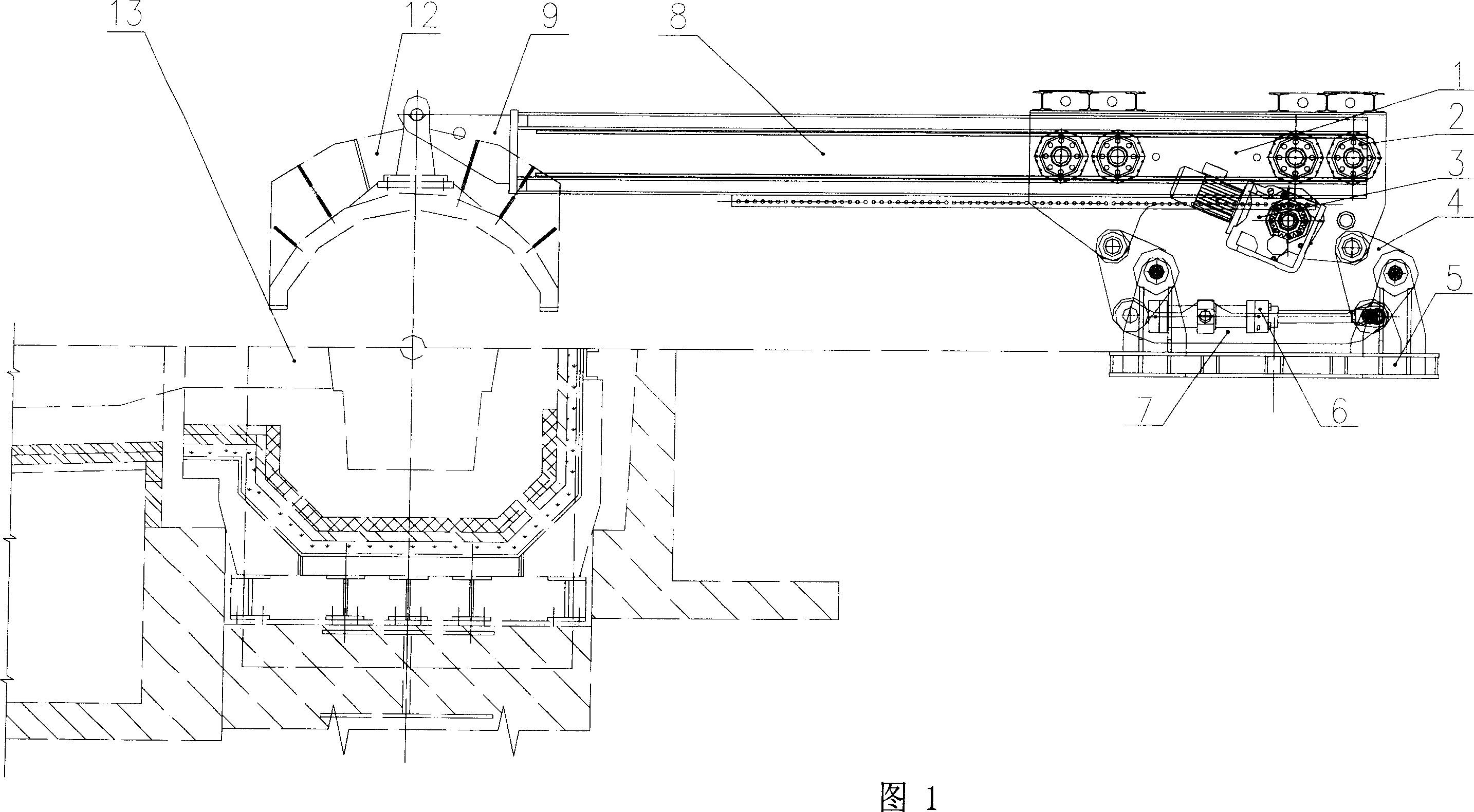
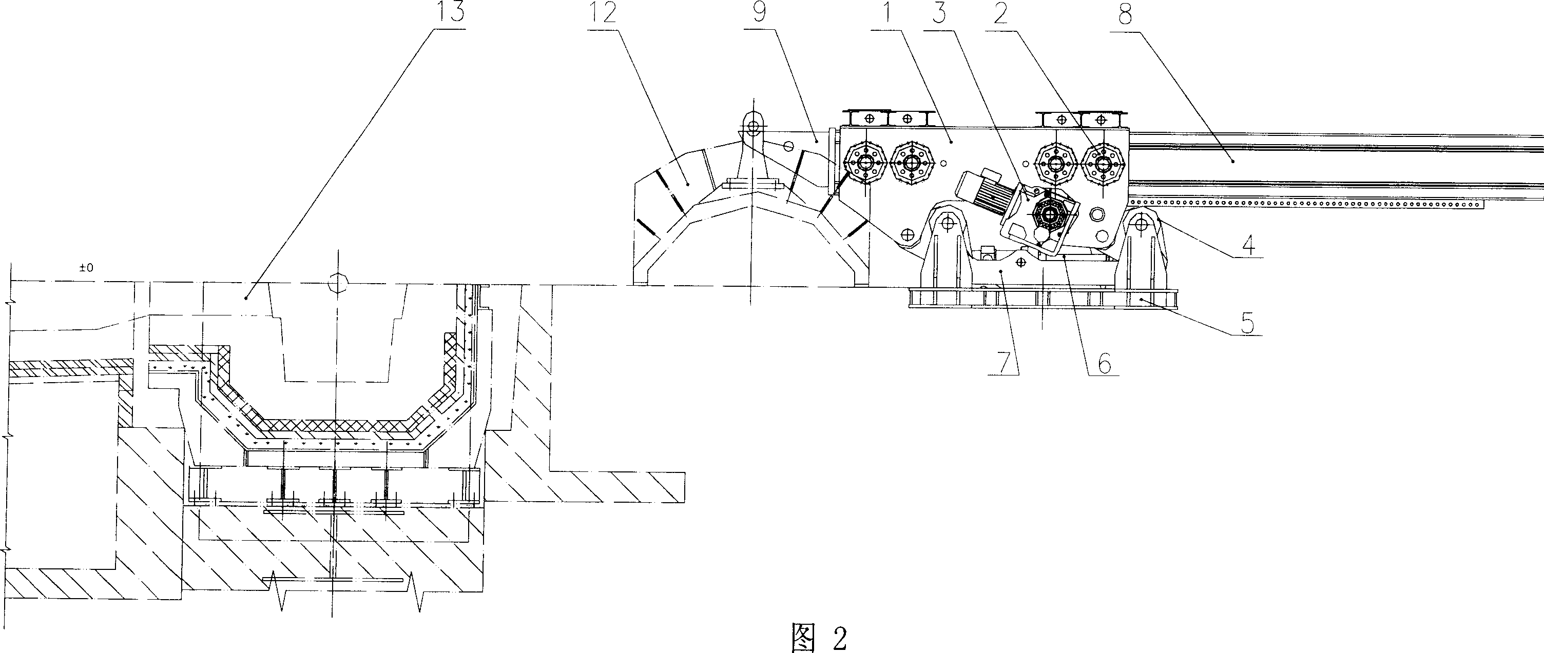
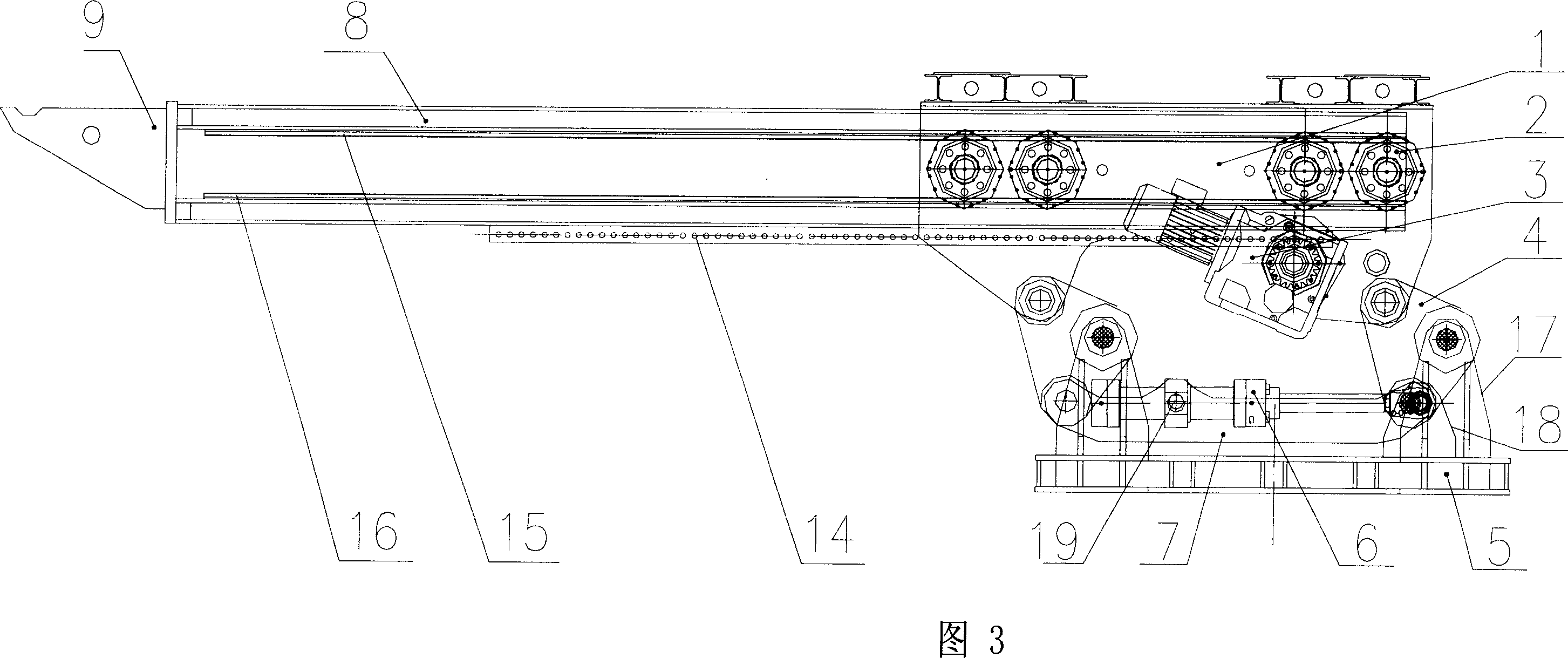
[0022] As shown in Fig. 3, Fig. 4, Fig. 5, Fig. 6, and Fig. 7, the low-type cover removing machine is composed of a lifting device, a frame 1, a horizontal movement mechanism, and a lifting hook 9, and the lifting hook 9 and the horizontal movement mechanism are formed. One end of the moving crossbeam 8 is fixedly connected; the horizontal moving mechanism includes a support wheel 2, a reduction motor 3, a moving crossbeam 8, a gear 10, a transmission shaft 11, a pin rack 14, an upper guide support track 15, a lower guide support track 16, and a moving crossbeam The left and right sides of 8 [the left side in Fig. 4 is the left side, and the right side is the right side] and the upper and lower parts are respectively provided with an upper guide support track 15 and a lower guide support track 16, and the upper guide support track 15 and the upper guide support track 15 on the left and right sides of the mobile crossbeam 8 All be provided with support wheel 2 between lower guid...


PUM


Abstract

This invention relates to a short cover manipulator, which comprises an elevation unit, a frame, a horizontal moving mechanism, and a hook. The horizontal moving mechanism comprises a bearing wheel, a speed reduction motor, a moving crossbeam, a gear, a transmission shaft, a pin rack, an upper guide-supporting rail, and a lower guide-supporting rail. The elevation unit comprises four bending connecting rods, a base, a hydraulic cylinder, two straight connecting rods, and an intermediate hinge axis. Four supporting frames are set at the four corners of the base. The first corners of the four bending connecting rods are hinged with the four supporting frames. The second corners of the four bending connecting rods are hinged with the left and right straight connecting rods. The third corners of the four bending connecting rods are hinged with the base. The cover manipulator has a low overall height and a low maximal height during working shift.

Description

technical field [0001] The invention relates to a cover removing machine, which is applied to the ditch cover of the iron ditch near the iron mouth section of the mobile blast furnace. Background technique [0002] Environmental protection requirements for blast furnace smelting are getting higher and higher. At present, new blast furnaces basically require the use of capping machines. The operation process is: firstly, the opening machine opens the iron hole, and then the uncapping machine moves the ditch cover to the top of the iron ditch and covers the iron ditch (to avoid dust, splashing, heat radiation, etc.), and after the molten iron is discharged, the uncapping machine moves the ditch cover to the top of the ditch. The cover was removed to make room, and the clay cannon blocked the iron mouth. Obviously, the use of the uncapping machine is the requirement and necessity of blast furnace iron mouth environmental protection. [0003] There are many types of capping ma...

Claims


Application Information

Patent Timeline
IPC IPC(8): C21B7/00
Inventor 盛正平胡雪萍徐祖敦盛汉桥张愉崔伟周强
Owner WISDRI ENG & RES INC LTD
Why Eureka
Try Eureka