Eureka AIR delivers breakthrough ideas for toughest innovation challenges, trusted by R&D personnel around the world.

Single fiber passive bus type optical fiber video frequency monitor system

A video monitoring system, bus-type technology, applied in the direction of television system, closed-circuit television system, cable transmission adapting to optical transmission, etc., can solve the problems of complex system structure, large power consumption, complex equipment, etc., and achieve system structure simplification , reduce power consumption, and simplify the structure

Inactive Publication Date: 2007-07-25
ANHUI WANTONG TECH
View PDF0 Cites 1 Cited by
  • Summary
  • Abstract
  • Description
  • Claims
  • Application Information

AI Technical Summary

Problems solved by technology

The optical transceiver mode is a point-to-point transmission method, which requires a pair of optical transceivers between each camera and the central device and occupies one optical fiber, and the system structure is complex
Optical fiber network structure, because the front end needs network equipment, cameras and related digital equipment, the equipment is complex and consumes a lot of power

Method used


Image

  • Single fiber passive bus type optical fiber video frequency monitor system
  • Single fiber passive bus type optical fiber video frequency monitor system

Examples


Embodiment Construction

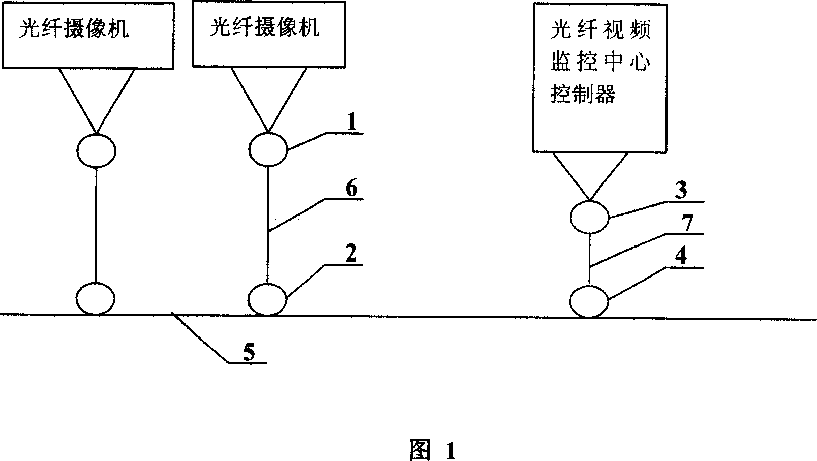
[0017] Referring to Figure 1, the system composition of the single-fiber passive bus-type optical fiber video surveillance system is as follows: install optical fiber cameras at each measured point, and use each optical fiber camera to communicate with branch wavelength division multiplexer 1 and branch branch splitter 2 in sequence. The branch to be tested is constituted in series, and a controller is set in the optical fiber video monitoring center, and the controller is sequentially connected with the monitoring center wavelength division multiplexer 3 and the monitoring center splitter 4 to form a monitoring branch in series; an optical fiber bus 5 is set, each The branch to be tested is connected to the optical fiber bus 5 in parallel through the branch splitter 2 , and the monitoring branch is connected to the optical fiber bus 5 in parallel through the monitoring center splitter 4 .

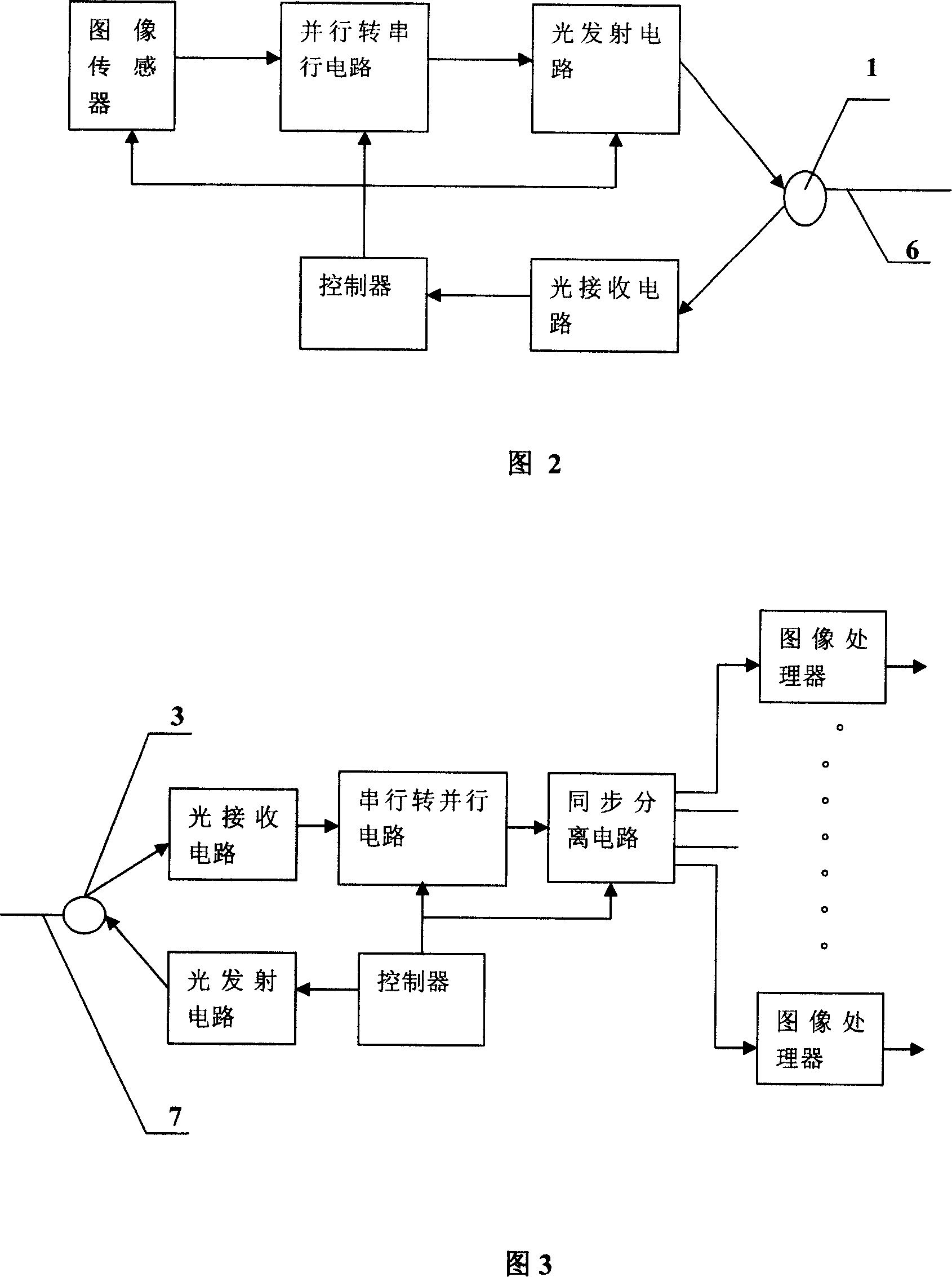
[0018] As shown in Figure 2 and Figure 3, a parallel-to-serial circuit is set between t...


PUM


Abstract

The invention features the following: respectively setting optical fiber video camera at each tested point; the optical fiber video cameras are combined with the branch wavelength division multiplexer and the branch demultiplexor to form a tested branch; setting a controller at the optical fiber monitor center which is combined with the monitor center multiplexer and the monitor center demultiplexor to form a monitor branch; setting a optical fiber bus where all tested branches and monitor branches are connected to; the parallel data signal outputted from image sensor is converted into series signal and is transmitted through the optical bus.

Description

technical field [0001] The invention relates to a video monitoring system, more specifically, relates to an optical fiber video monitoring system. Background technique [0002] With the advancement of society and the acceleration of the modernization process, the field of video surveillance systems is expanding day by day. Many systems need to transmit video signals over long distances, and fiber optic video surveillance systems are increasingly used. At present, such systems mostly have two structures. One is to use the optical transceiver method, and the other is the optical fiber network. These two structures are not very suitable for some applications that require multi-point and long-distance transmission. For example, a video surveillance system along a highway requires a camera every few kilometers. And since there is no power supply except near the toll stations along the way, the power consumption of the front-end monitoring equipment is required to be as small a...

Claims


Application Information

Patent Timeline
IPC IPC(8): H04N7/18H04N7/22
Inventor 王以直李晓军葛春风
Owner ANHUI WANTONG TECH
Why Eureka
Eureka Blog
Learn More