
Polishiing apparatus and polishiing method

A technology of a grinding device and a grinding method, which is applied to grinding machines, grinding workpiece supports, grinding machine parts, etc., can solve problems such as defective products, and achieve the effects of low frictional resistance, preventing damage to substrates, and preventing deflection

Inactive Publication Date: 2007-07-25
MITSUBOSHI DIAMOND IND CO LTD
View PDF3 Cites 4 Cited by
  • Summary
  • Abstract
  • Description
  • Claims
  • Application Information

AI Technical Summary

Problems solved by technology

This residual stress will cause chipping after scribing and cutting, and may cause product defects after productization

Method used


Image

  • Polishiing apparatus and polishiing method
  • Polishiing apparatus and polishiing method
  • Polishiing apparatus and polishiing method

Examples


Embodiment Construction

[0113] Embodiment 1

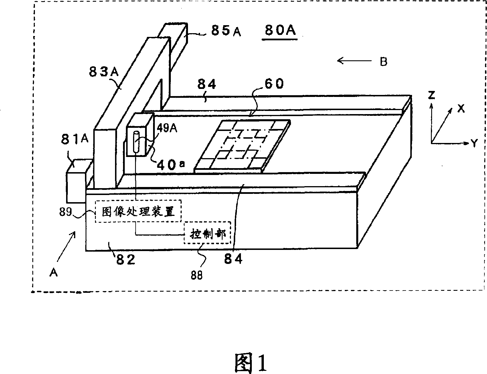
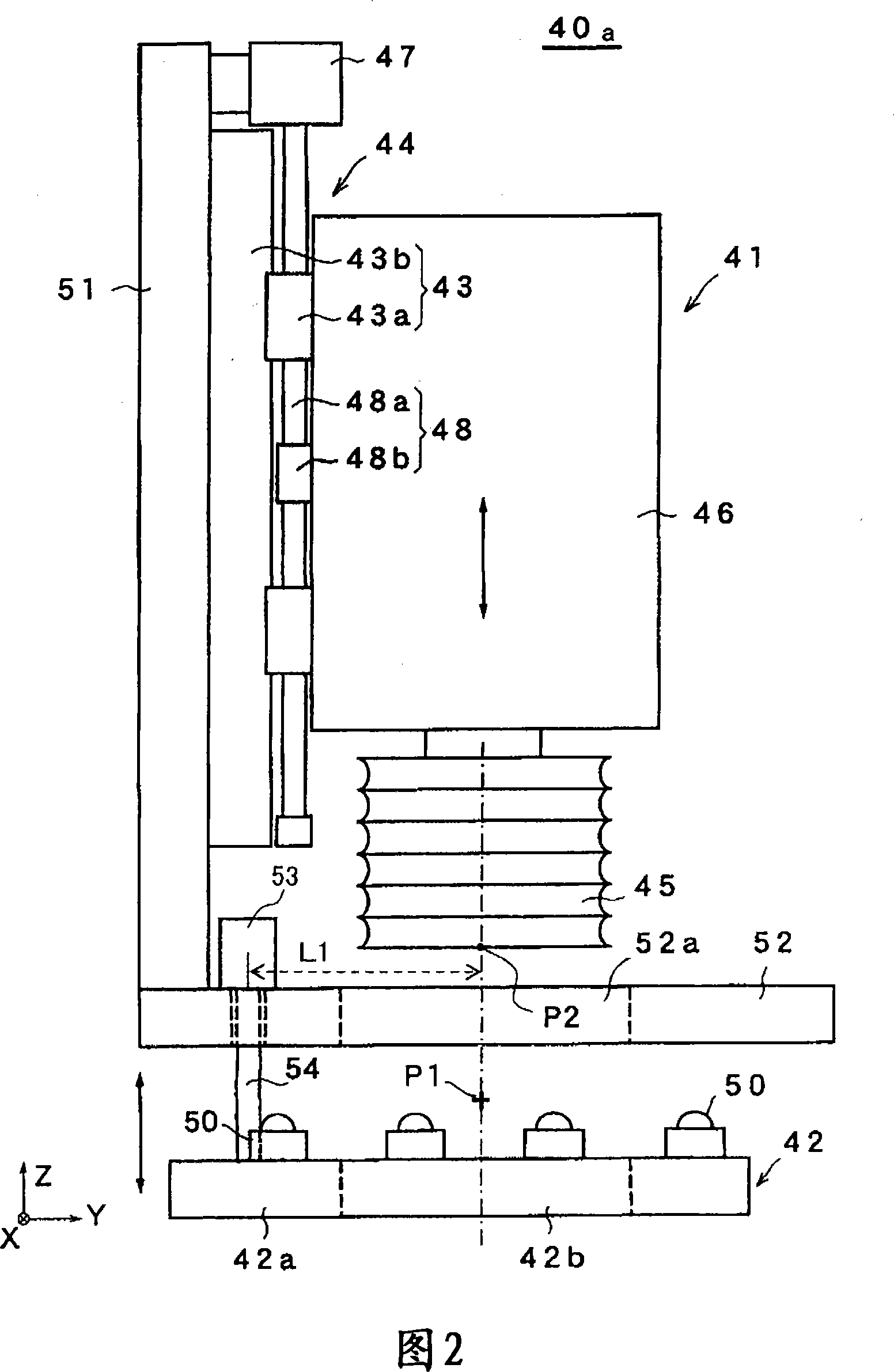
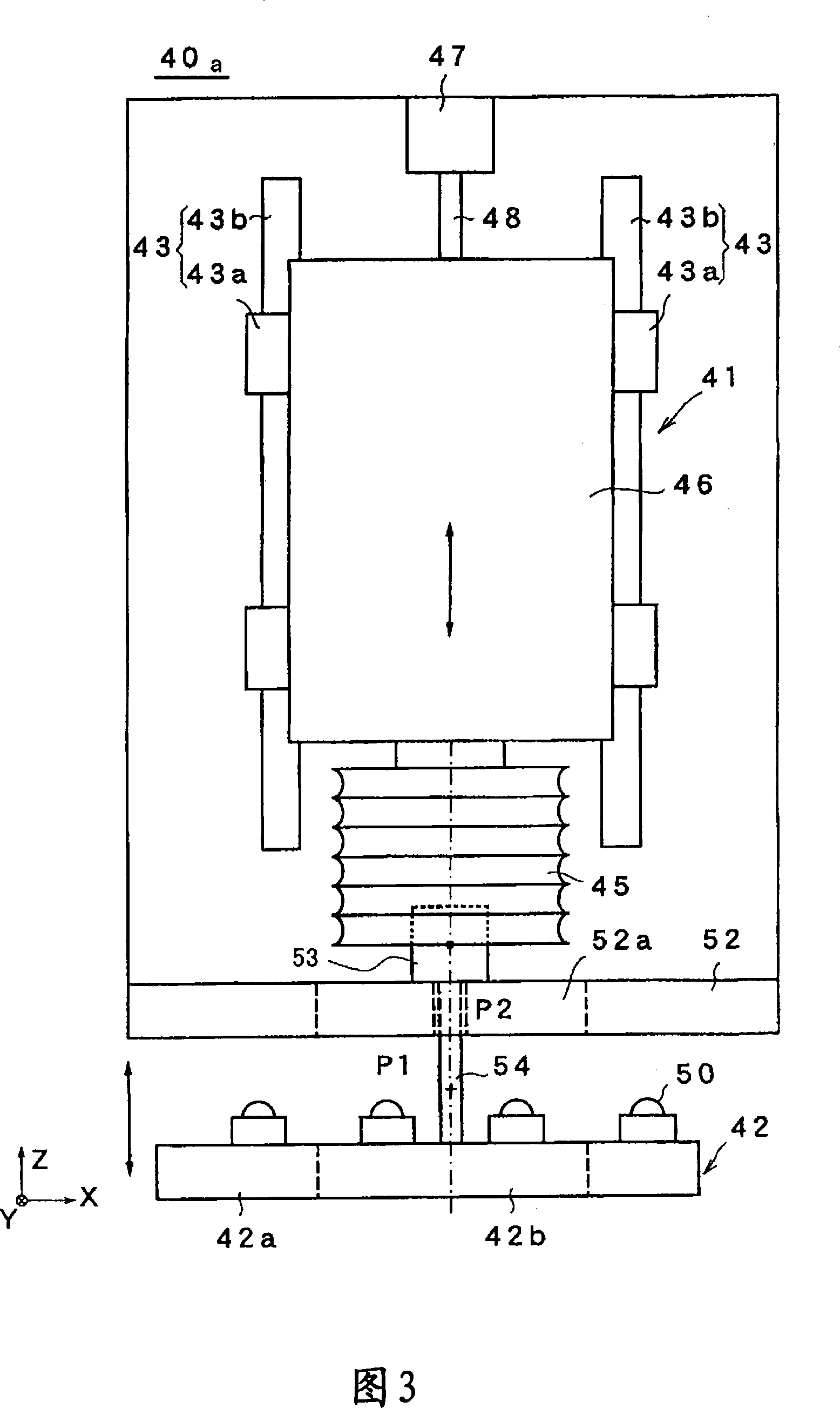
[0114] Fig. 1 is a schematic perspective view showing a schematic configuration of a polishing apparatus according to Embodiment 1 of the present invention. The grinding device 80A is provided with a base 82, a stage unit 60 disposed on the base 82 for holding a substrate whose end surface is to be ground, and a grinding unit 40a for grinding the end surface of the substrate held by the stage unit 60. , a grinding unit holder 83A for holding the grinding unit 40a, a pair of LM guides 84 for guiding the grinding unit holder 83A, a grinding unit holder for moving the grinding unit holder 83A along the respective LM guides 84 Moving mechanism 81A, polishing unit moving mechanism 85A for moving polishing unit 40a held by polishing unit holder 83A, imaging device 49A attached to polishing unit 40a, control unit 88, and image processing device 89.

[0115] The base 82 has a horizontal rectangular shape above. In addition, in the following description, the sh...


PUM


Abstract

The polishing apparatus capable of accurately chamfering the end face parts of a large-sized substrate is installed on a table unit in which the substrate is placed. The substrate is fixedly held on the table unit (60) under a specified reference condition. A first polishing unit (40a) comprises a polishing grinding wheel polishing the end faces of the substrate held on the table unit (60) and a substrate side edge part support means supporting the side edge part lower surface of the substrate near the end faces of the substrate polished by the polishing grinding wheel. The first polishing unit (40a) is moved by a first polishing unit moving means (85A) along the end faces of the substrate together with the substrate side edge part support means under the condition that the polishing grinding wheel polishes the end faces of the substrate.

Description

technical field [0001] The invention relates to a grinding device and a grinding method for grinding the end face of the outer side of a substrate. Background technique [0002] Fragile substrates such as semiconductor wafers, glass substrates, quartz substrates, and ceramic substrates usually require chamfering of the end faces of the substrates. In addition, the bonded substrates obtained by bonding the single substrates also need to be chamfered on the end faces of the substrates. Such a bonded substrate is particularly commonly used for a panel for a liquid crystal display (LCD), which is a type of flat panel display (FPD). In addition, the laminated substrate is also used for the plasma display panel (PDP) and organic EL panel of the FPD other than the panel for the liquid crystal display (LCD), or for the substrate of the transmissive liquid crystal projector included in the liquid crystal projector, reflective Type liquid crystal projector substrate, etc. Furthermo...

Claims


Application Information

Patent Timeline
Patent Type & Authority Applications(China)
IPC IPC(8): B24B9/10B24B41/06B24B9/00B24B49/12
CPCB24B9/065B24B41/06B24B9/10B24B41/00B24B49/12
Inventor 江岛谷彰
Owner MITSUBOSHI DIAMOND IND CO LTD
Learn More