Communication device test signal generating apparatus and communication device test signal generating method

A technology for testing signals and communication equipment, applied in transmission monitoring, digital transmission systems, electrical components, etc., can solve the problems of increasing storage capacity, a lot of work and time consumption, and increasing the storage capacity of waveform memory.

Inactive Publication Date: 2007-07-25
ANRITSU CORP
View PDF2 Cites 5 Cited by
  • Summary
  • Abstract
  • Description
  • Claims
  • Application Information

AI Technical Summary

Problems solved by technology

However, there is a problem that it is necessary to prepare waveform data whose frequency characteristics have been corrected according to the frequency compensation at each frequency compensation after securing a high level of accuracy in each frequency hopping
Therefore, there is a problem of greatly increasing the storage capacity required for a memory such as a hard disk drive for storing corresponding signal waveforms of those test signals
Therefore, there is a problem: greatly increasing the storage capacity of the waveform memory
[0018] Also, there is a problem that a lot of work is required for an operation of generating signal waveforms of test signals having different waveform data, different signal levels, and different frequencies for each of various communication tests of mobile phones as test objects
[0019] Also, since the frequency characteristics of each mobile phone serving as a test object are different, there is a problem that a large amount of work and time consumption are required for generating a test signal having a different frequency characteristic for each mobile phone serving as a test object. signal waveform
Therefore, the continuity of the waveform data when switching the waveform of the test signal is required, and in many cases, the same data is repeatedly used several times depending on the test signal, so there is a problem that the function of repeatedly outputting the same data several times is required, In order to ensure the continuity of the waveform data when switching

Method used


Image

  • Communication device test signal generating apparatus and communication device test signal generating method
  • Communication device test signal generating apparatus and communication device test signal generating method
  • Communication device test signal generating apparatus and communication device test signal generating method

Examples


no. 1 example

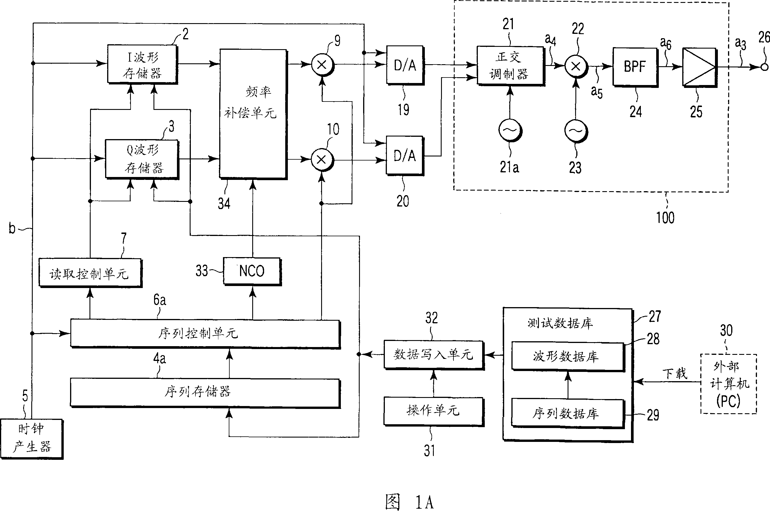
[0175] First, a first embodiment of a test signal generating apparatus for a communication device according to the present invention will be specifically described with reference to FIGS. 1A and 2-8.

[0176] FIG. 1A is a block diagram showing a schematic configuration of a first embodiment of a test signal generating apparatus for communication equipment according to the present invention.

[0177] FIG. 2 is a table showing the contents stored in the sequence memory 4a provided in the test signal generating device of FIG. 1A.

[0178] 3A and 3B are graphs shown for explaining the relationship between frequency characteristics and modulation signal levels in the test signal generating apparatus of FIG. 1A.

[0179] FIG. 4 is a diagram for explaining frequency hopping of a GSM signal used in a jamming wave immunity test performed in the present invention.

[0180] FIG. 5 is a diagram for explaining storage contents in a pair of waveform memories 2 and 3 formed in the test sign...

no. 2 example

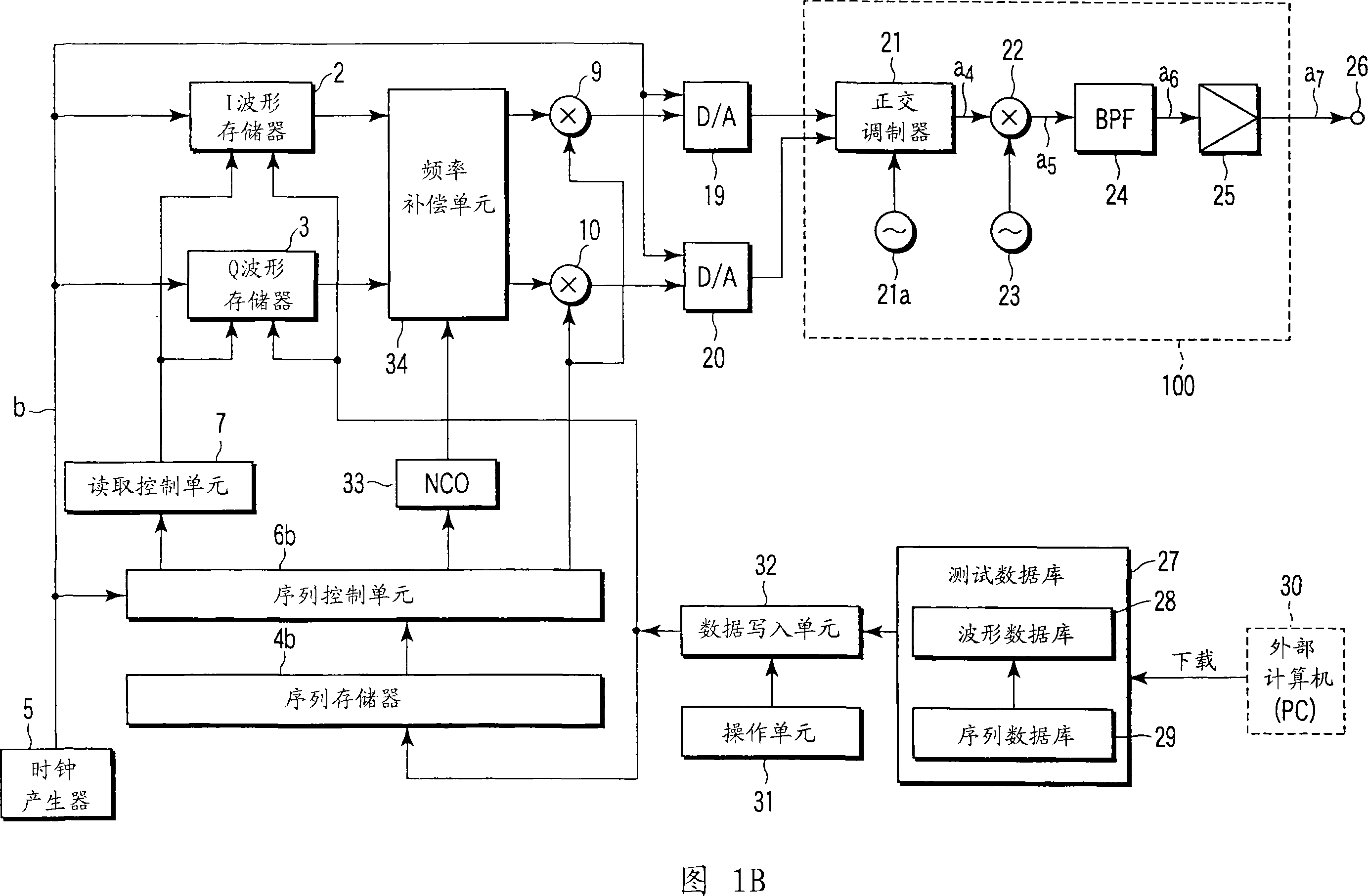
[0247] Next, a second embodiment of the test signal generating apparatus for communication equipment according to the present invention will be specifically described with reference to FIGS. 1B, 9 and 10. FIG.

[0248] FIG. 1B is a block diagram showing a schematic configuration of a test signal generating apparatus for a communication device according to a second embodiment of the present invention.

[0249] FIG. 9 is a diagram for explaining storage contents in the sequence memory 4b provided in the test signal generating device of FIG. 1B.

[0250] FIG. 10 is a diagram for explaining an arrangement of test signals output from the test signal generating device of FIG. 1B .

[0251] In FIG. 1B, the same components as those of the test signal generating apparatus for a communication device according to the first embodiment shown in FIG. 1A are denoted by the same reference numerals, and detailed description of overlapping parts will be omitted.

[0252] Therefore, the test si...

no. 3 example

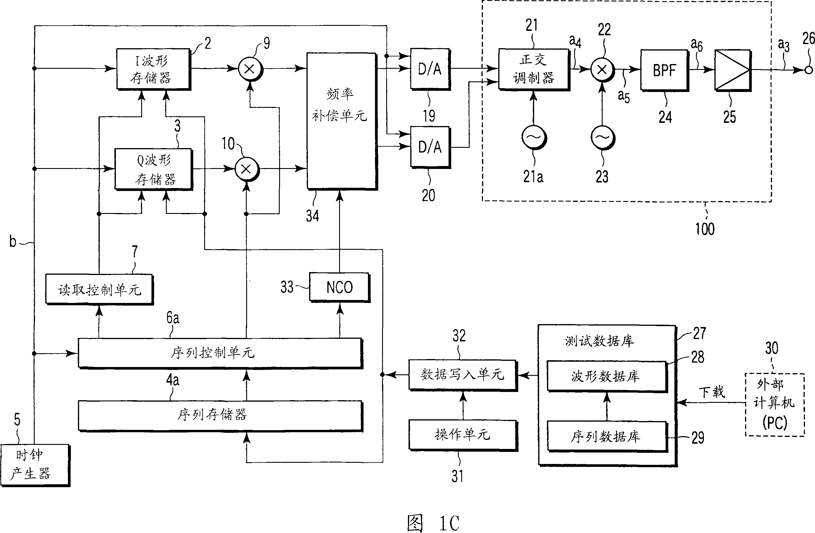
[0259] Next, a third embodiment of the test signal generating apparatus for communication equipment according to the present invention will be specifically described with reference to FIG. 1C.

[0260] FIG. 1C is a block diagram showing a schematic configuration of a third embodiment of the test signal generating apparatus for communication equipment related to the present invention.

[0261] In FIG. 1C, the same components as those of the test signal generating apparatus for a communication device according to the first embodiment shown in FIG. 1A are denoted by the same reference numerals, and detailed description of overlapping parts will be omitted.

[0262] Therefore, the difference between the test signal generating apparatus for communication equipment according to the third embodiment shown in FIG. 1B and the test signal generating apparatus for communication equipment of the first embodiment shown in FIG. 1A at the digital stage from the pair of waveform memories 2, 3 u...


PUM


Abstract

A communication device test signal generating apparatus wherein a sequence memory stores an order in which to read unit data including I and Q waveform data; read addresses; first sequence information including a desired signal level to be set in the unit data; and second sequence information including a frequency offset, and wherein the first and second sequence information stored in the sequence memory are sequentially used to apply a plurality of steps of frequency offsets to the I and Q waveform data in a digital stage preceding a D/A converter at predetermined frequency intervals with a predetermined carrier frequency being referenced, thereby outputting the frequency hopping test signal.

Description

technical field [0001] The present invention relates to a test signal generation device for communication equipment and a test signal generation method for communication equipment, in particular to such a test signal generation device for communication equipment and a test signal generation for communication equipment Methods by which a modulated signal comprising at least one or more elements of data is generated as a test signal for a communication device. Background technique [0002] When a communication device such as a mobile communication terminal (such as a mobile phone) is newly developed, some kind of failure may be brought about in the mobile phone in operation, or the mobile phone in operation has terminated a predetermined service duration in some cases time. In this case, a communication test is required to confirm whether various functions of these mobile phones function normally. [0003] Specifically, there is a need for a communication test for confirming...

Claims


Application Information

Patent Timeline
Patent Type & Authority Applications(China)
IPC IPC(8): H04B1/713H04B1/707H04L27/00
CPCH04B17/0085H04B2001/7154H04B1/715
Inventor 熊木成央大谷育也秋山典洋
Owner ANRITSU CORP
Why Eureka
Try Eureka