Tension equipment of continuous mill system

A tension device and tension technology, applied in the direction of braking/tightening device, tension/pressure control, etc., can solve the problems of large fluctuation of tension control, affecting production output and product quality, and complex control system.

Inactive Publication Date: 2007-08-01
郑红专 +1
View PDF0 Cites 14 Cited by
  • Summary
  • Abstract
  • Description
  • Claims
  • Application Information

AI Technical Summary

Problems solved by technology

[0010] The purpose of the present invention is to provide a tension device in the continuous rolling system, which can effectively solve the technical defects of the prior art continuo

Method used


Image

  • Tension equipment of continuous mill system
  • Tension equipment of continuous mill system

Examples


no. 1 example

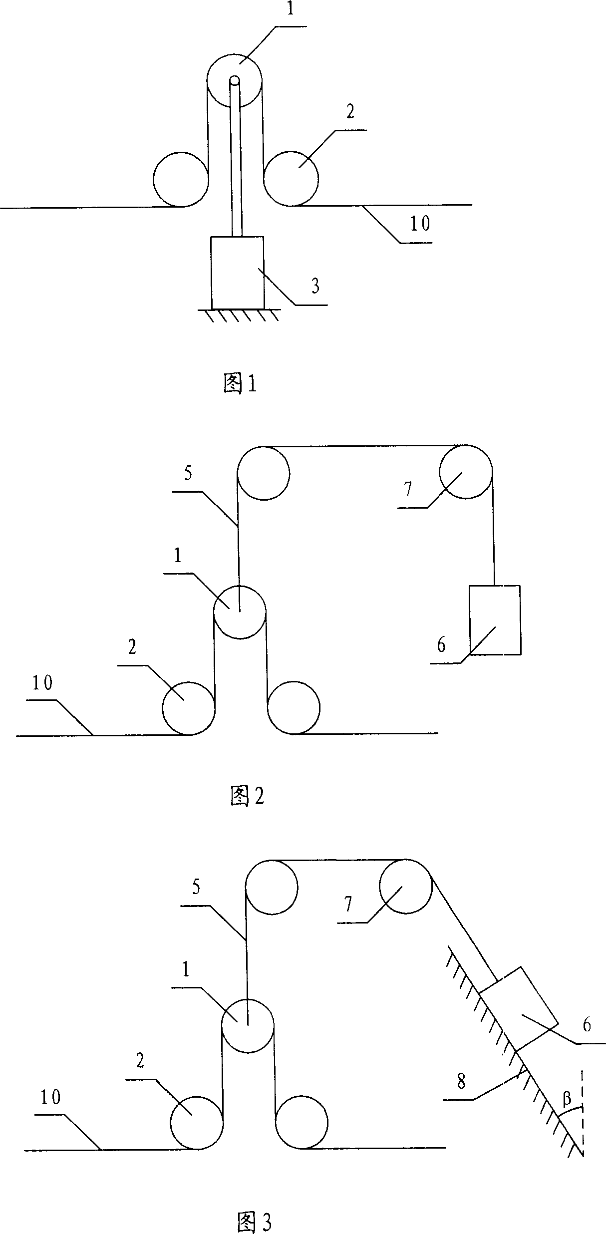
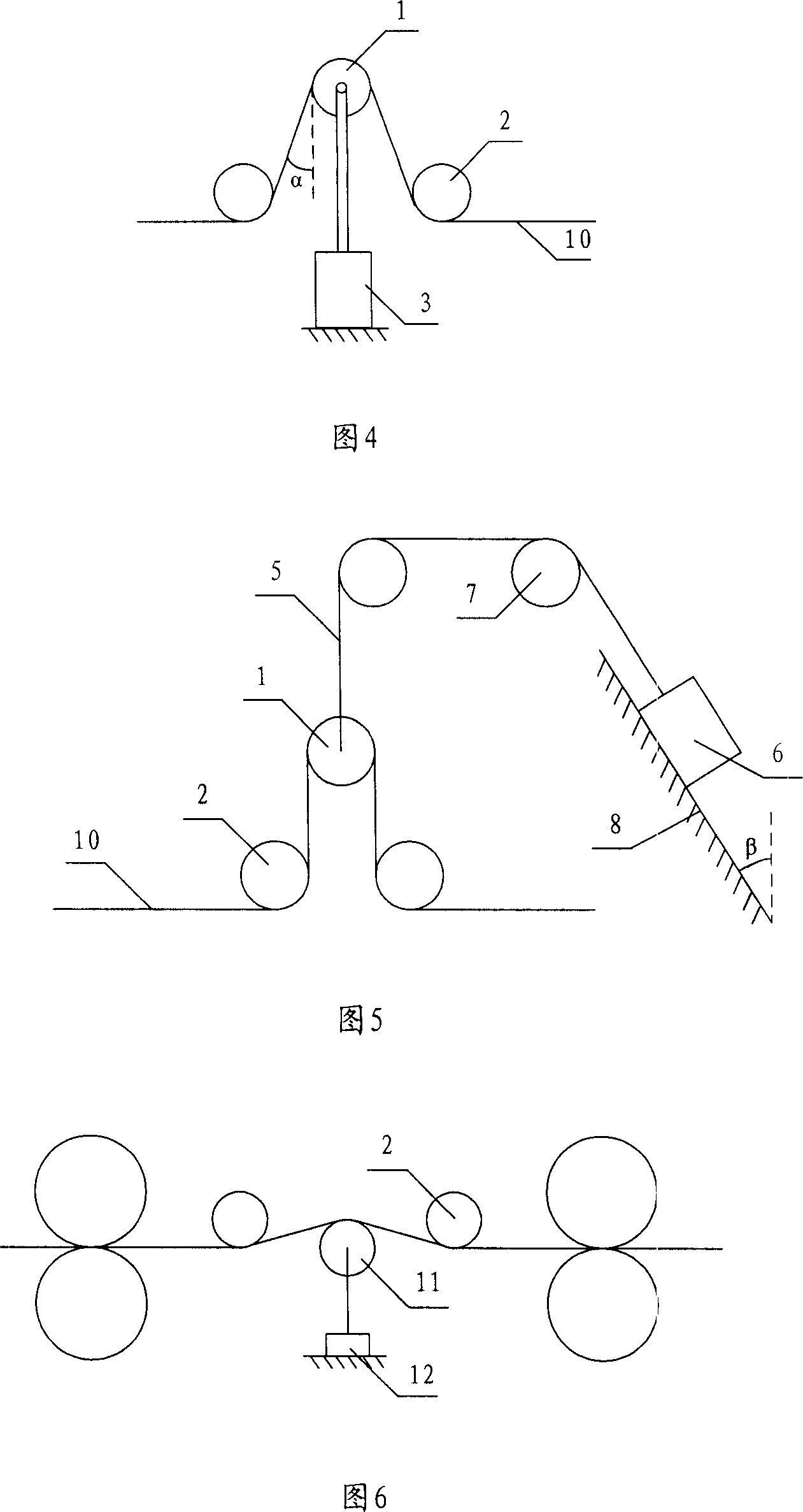
[0028] Fig. 1 is a schematic structural diagram of the first embodiment of the present invention. As shown in Figure 1, the tension device in the continuous rolling system of this embodiment includes a floating roller 1 and two guide rollers 2 located on both sides of the floating roller 1, and the two guide rollers 2 are responsible for guiding the rolling piece 10 to move from left to right , the floating roll 1 is used to support the rolled piece 10, and the rolled piece between the floating roll 1 and the two guide rolls 2 is vertical. The floating roller 1 is connected with the hydraulic device 3 with constant support force output, so that the floating roller 1 can move up and down according to the change of the tension of the rolled piece, and the tension of the rolled piece can be kept constant by changing the length of the rolled piece between the floating roller and the two guide rollers .

[0029] When the tension of the rolling piece 10 between the two rolling mill...

no. 2 example

[0031] Fig. 2 is a schematic structural diagram of a second embodiment of the present invention. As shown in Figure 2, the tension device in the continuous rolling system of this embodiment includes a floating roll 1 and two guide rolls 2 positioned on both sides of the floating roll 1, and the two guide rolls 2 are responsible for guiding the rolling piece 10 to move from left to right , the floating roll 1 is used to support the rolled piece 10, and the rolled piece between the floating roll 1 and the two guide rolls 2 is vertical. The floating roller 1 is connected to a counterweight 6 through the suspension cable 5 and the fixed pulley block 7. The counterweight 6 has a constant weight and produces a constant tension on the suspension cable 5 and the floating roller 1, so that the floating roller 1 moves up and down according to the tension change of the rolled piece , by changing the length of the rolled piece between the floating roller and the two guide rollers to keep ...

no. 3 example

[0034] Fig. 3 is a schematic structural diagram of a third embodiment of the present invention. As shown in FIG. 3 , this embodiment is a structural improvement of the second embodiment shown in FIG. 2 . The difference is that the weight body is arranged on an inclined plane 8 , and the included angle between the inclined plane 8 and the vertical direction is β. In this embodiment, by setting the slope, the tension of the counterweight body 6 acting on the suspension cable 5 can be changed according to the change of the β angle. When the set constant tension needs to be changed, the β angle can be adjusted to change the 5 pairs of floating rollers of the suspension cable. 1, but no matter how the slope β angle is adjusted, the tension of the counterweight 6 acting on the suspension cable 5 is constant during the operation of the continuous rolling system.


PUM


Abstract

The invention involves a tension device of tandem rolling system. It includes two guide rollers guiding rolling pieces move, floating roller is equipped between said two guide rollers and supports rolling pieces with constant force and makes the rolling pieces stretching force constant through moving up and down, the rolling pieces between said floating roller and said two guide rollers is vertical. Said floating roller can be connected with a hydraulic means which has constant support force, also can be connected with a counterweight body with constant stretching force through hanger rope. The invention proposes a technology program which ensures rolling pieces stretching force constant in rolling plant through changing storage rolling pieces length in rolling mill plant, has characteristics of simple structure, separately adjustment, fast dynamic response and high control precision, etc, it effectively solves the enormous puzzle and technical difficulty stopping tandem rolling technique development for years and years.

Description

technical field [0001] The invention relates to a tension device in a continuous rolling system, in particular to a device for constant tension of rolled pieces between rolling mills. Background technique [0002] In the continuous rolling system, it is very important to keep the tension of the steel strip between the rolling mills constant. The constant tension of the steel strip can not only ensure that there will be no steel drawing or stacking phenomenon that makes continuous rolling difficult during the rolling process, but also make the continuous rolling system in the continuous rolling system. Work under the optimal setting state to roll out high-quality products. [0003] Figure 6 is a tension measurement device commonly used in continuous rolling systems, including tension rolls, guide rolls and pressure sensors located on both sides of the tension rolls. Its working principle is: when the tension of the rolled piece changes, the pressure sensor 12 sends the press...

Claims


Application Information

Patent Timeline
IPC IPC(8): B21B37/48B21B39/08
Inventor 郑红专赵林珍
Owner 郑红专
Why Eureka
Try Eureka