Laser welding head

A technology of laser welding and working head, applied in laser welding equipment, welding equipment, welding equipment and other directions, can solve difficult, cumbersome and other problems, and achieve the effect of good pressing effect

Inactive Publication Date: 2007-08-01
BEIJING UNIV OF TECH
View PDF0 Cites 18 Cited by
  • Summary
  • Abstract
  • Description
  • Claims
  • Application Information

AI Technical Summary

Problems solved by technology

However, due to the irregularity of the surface deformation of the welding workpiece, it is very difficult and cumbersome to control the welding head (including wire feeding head, powder feeding head and gas protection head) through laser welding equipment so that the distance between the end and the surface of the workpiece remains unchanged. Work

Method used


Image

  • Laser welding head
  • Laser welding head
  • Laser welding head

Examples


Embodiment 1

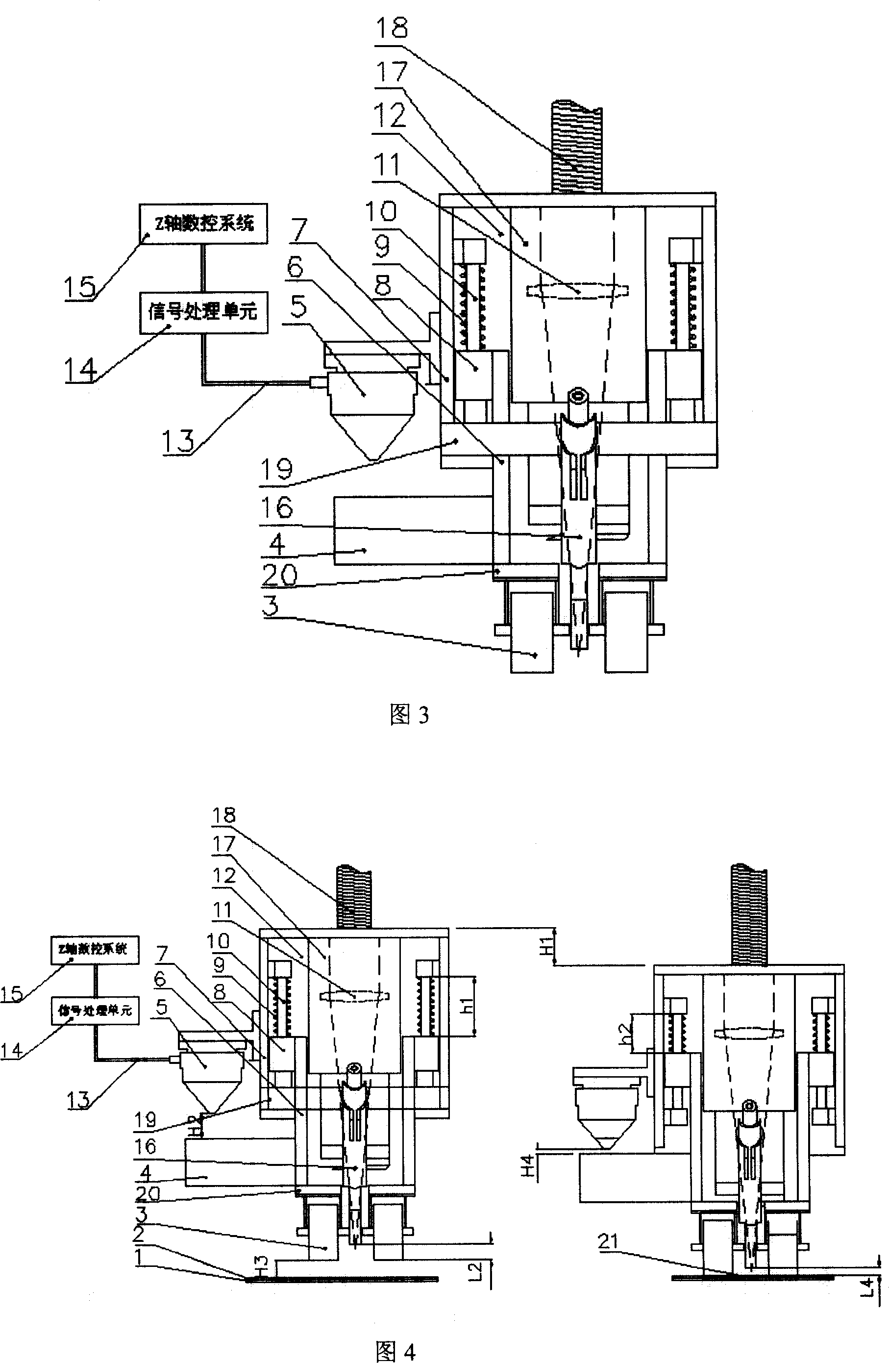
[0028] The schematic diagram of the structure of Embodiment 1 of the present invention is shown in Figure 3. The welding head includes a welding nozzle 16, a welding head 17, a frame plate 12, a static support plate 7, a dynamic support plate 6, a guide rail 10, a spring 9, and a slider 8 , pressing part 3, height tracking sensor 5, height tracking reference surface 4, signal processing unit 14, Z-axis control system; wherein: welding head 17 is installed on the frame plate 12, and its axis coincides with the laser transmission axis, and the frame The plate 12 is connected with the Z-axis transmission shaft 18, the static support plate 7 is distributed on both sides of the welding head 17, and is installed on the frame plate 12, the guide rail 10 is installed on the inner side of the static support plate, the spring 9 is installed on the guide rail 10, and the slider 8 is installed on the bottom of the guide rail 10, the spring 9 is set on the outer circumference of the guide r...

Embodiment 2

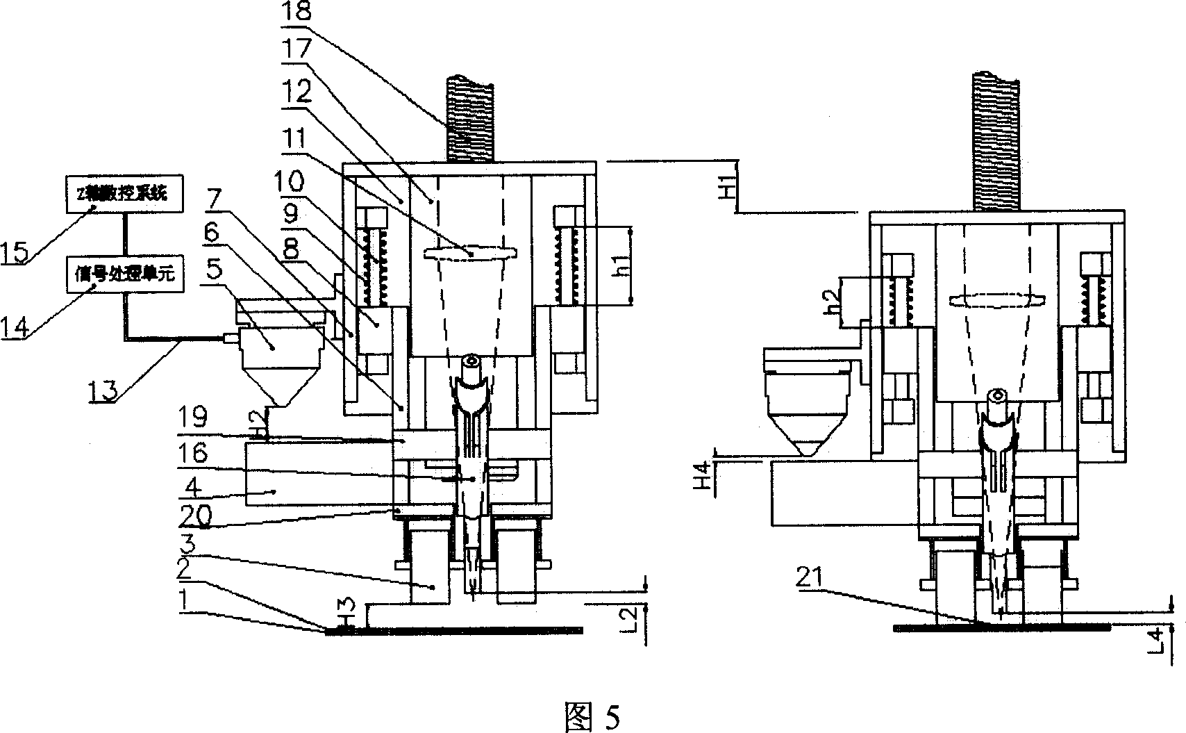
[0037] Referring to FIG. 3 for Embodiment 2 of the present invention, the structure of Embodiment 2 is the same as that of Embodiment 1, except that the welding nozzle support plate 19 is installed on the movable support plate 6 . Its working principle diagram is shown in Figure 5. Since the welding nozzle support plate 19 is installed on the movable support plate 6, the relative position of the welding nozzle 16 and the bottom surface of the pressing part 3 remains unchanged, that is, L2=L4, which can also reflect H3 has nothing to do with the topographic features of the welded workpiece. Since the height tracking sensor 5 can ensure that the bottom of the pressing part 3 is always on the surface of the upper workpiece 2 during the welding process, it is guaranteed that the welding nozzle 16 is always constant relative to the surface of the upper workpiece 2 during the welding process, thereby ensuring that the welding head While maintaining a constant pressing force on the w...


PUM


Abstract

The invention involves a laser welding work head which belongs to laser materials welding technology field. It includes welding nozzle (16) and welding joints (17), it is characterized by: it also includes rack plate (12), static support plate (7), dynamic support plate (6), guide rail (10), spring (9), sliding block(8) and clamping components (3), height tracking sensor (5), high tracking reference plane (4), signal processing unit (14), Z-axle control system; Among them, the high tracking sensor (5) is installed on the outboard of static support plate (7) and under the high tracking reference plane which out the dynamic support plate (6).The beneficial effect of the invention is: in laser welding process, it ensures the clamping components (3) presses the workpiece tightly in constant pressure, ensures the relative position of laser welding nozzle to workpiece surface is constant and ensures the reliability and stability of laser welding quality.

Description

technical field [0001] The invention relates to a laser welding working head, which belongs to the technical field of laser material welding. Background technique [0002] Laser welding has outstanding advantages such as high energy density, fast welding speed, large weld depth-to-width ratio, good joint performance, and small deformation of the welded structure. With the development of industrial lasers, laser welding technology has been more and more widely used. [0003] The laser welding process requires that the welding workpiece be well clamped during the welding process to ensure that the welding process is stable and smooth. [0004] The workpiece clamping device is generally installed on the worktable where the workpiece is placed, arranged on both sides of the welded part, and presses the welded workpiece tightly. This clamping device has a relatively complicated structure and occupies a large space. For the undulating surface of the welding workpiece, the tooli...

Claims


Application Information

Patent Timeline
Patent Type & Authority Applications(China)
IPC IPC(8): B23K26/20B23K26/42B23K26/08B23K37/053B23K26/21B23K26/70
Inventor 肖荣诗武强杨武雄
Owner BEIJING UNIV OF TECH
Why Eureka
Try Eureka