

Double-feed type variable speed constant frequency wind turbine generator sets
A wind turbine, variable speed and constant frequency technology, applied in wind turbine combination, wind turbine, wind turbine control and other directions, can solve the problems of complex control implementation, complex vector decoupling calculation, and insignificant control target effect.
- Summary
- Abstract
- Description
- Claims
- Application Information
AI Technical Summary
Problems solved by technology
Method used
Image

Examples
Embodiment 1
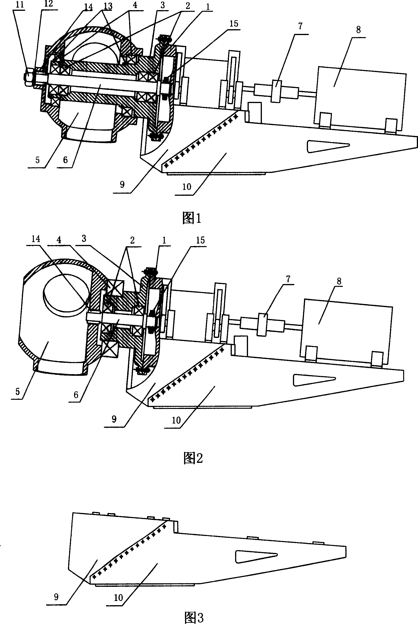
[0093] Embodiment 1: as shown in Figure 1, the present invention comprises front nacelle chassis 9, rear nacelle chassis 10, generator 8, speed-up box 1 and wind wheel, and wind wheel comprises wheel hub 5 and blade, three mouths of blade and wheel hub 5 connection, the connection surface between the front engine room chassis 9 and the rear engine room chassis 10 is an inclined plane, the rear engine room chassis 10 is fixed on the tower, the generator 8 is placed on the rear engine room chassis 10, and the speed increaser box 1 is placed on the front engine room chassis 9 Above: The generator 8 is connected to the speed-up box 1 through the coupling 7, and the speed-up box 1 and the hub 5 are connected through the end cover 3.
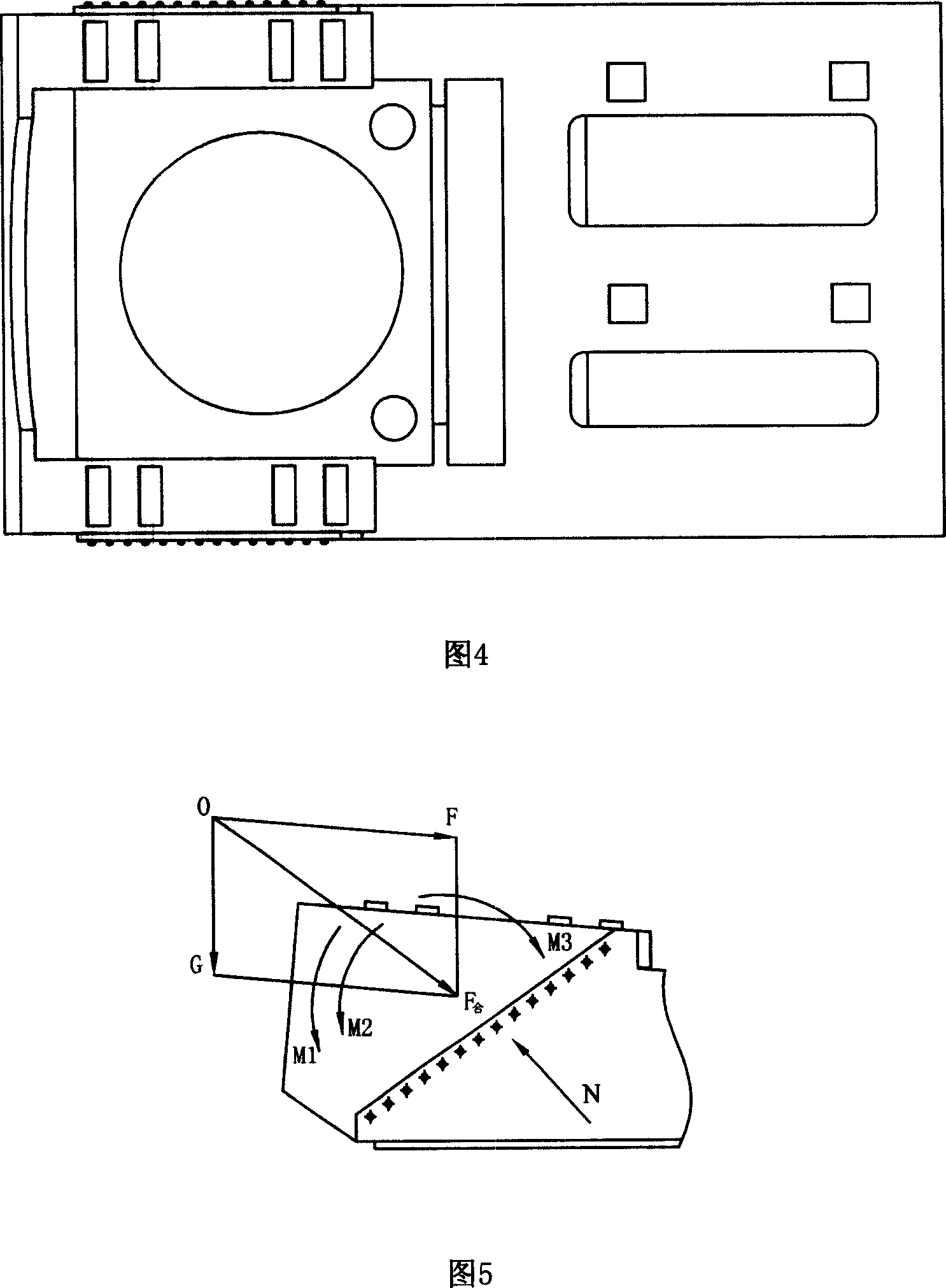
[0094] As shown in Fig. 3 and Fig. 4, the inclination angle of the inclined plane between the front nacelle chassis 9 and the rear nacelle chassis 10 in this example is 40°; the front nacelle chassis 9 is fixed on the rear nacelle chassis 10 by bolts a...
Embodiment 2
[0106] Embodiment 2: the present invention comprises front nacelle chassis 9, rear nacelle chassis 10, generator 8, speed-increasing box 1 and wind wheel, and the connecting surface between front nacelle chassis 9 and rear nacelle chassis 10 is an inclined plane, and rear nacelle chassis 10 is fixed On the tower, the generator 8 is placed on the rear engine room chassis 10, and the speed increasing box 1 is placed on the front engine room chassis 9; They are connected by end cap 3.
[0107] As shown in Fig. 3 and Fig. 4, the inclination angle of the inclined plane between the front nacelle chassis 9 and the rear nacelle chassis 10 in this example is 38°; the front nacelle chassis 9 is fixed on the rear nacelle chassis 10 by bolts and hooks thereon . Due to the effect of the inclined plane and the crotch, the force borne by the front section nacelle chassis 9 acts on the inclined plane, and the power is transmitted to the tower through the inclined plane.
[0108] Spindle dia...
Embodiment 3
[0115] Embodiment 3: The structure of this example is the same as that of Embodiment 2, as shown in Figure 2, except that the inclination angle of the slope between the front cabin chassis 9 and the rear cabin chassis 10 is 43 °;
[0116] Spindle diameter: d ≥ A 0 p / n 3 ≥ 334.2 mm
[0117] A 0 = 9550000 / 0.2 [ τ ] T 3 ,
[0118] [τ] T ——Allowable torsional shear stress, 200Mpa,
[0119] P——the power transmitted by the shaft, 1000Kw,
[0120] n - the rotational speed of the shaft, 1600r / min.
[0121] The structure of the end cover 3 in this example, as shown in Figure 2, is...
PUM
 Abstract
Description
Claims
Application Information