Method for separating thermal noise, shot noise and intensity noise of optical fiber gyroscope

A fiber optic gyroscope and shot noise technology, which is applied in the separation of shot noise and intensity noise, and in the field of fiber optic gyroscope thermal noise, can solve problems such as poor reliability of results and limited accuracy

Inactive Publication Date: 2007-08-01
ZHEJIANG UNIV
View PDF0 Cites 15 Cited by
  • Summary
  • Abstract
  • Description
  • Claims
  • Application Information

AI Technical Summary

Problems solved by technology

Theoretically, it only needs to test the noise intensity under three different intensities, and get three equations to solve the equations to get three noise sizes, but the accuracy of this method is limited, and the reliability of the results is poor

Method used


Image

  • Method for separating thermal noise, shot noise and intensity noise of optical fiber gyroscope
  • Method for separating thermal noise, shot noise and intensity noise of optical fiber gyroscope

Examples


Embodiment Construction

[0043] Below in conjunction with accompanying drawing and embodiment the present invention will be further described:

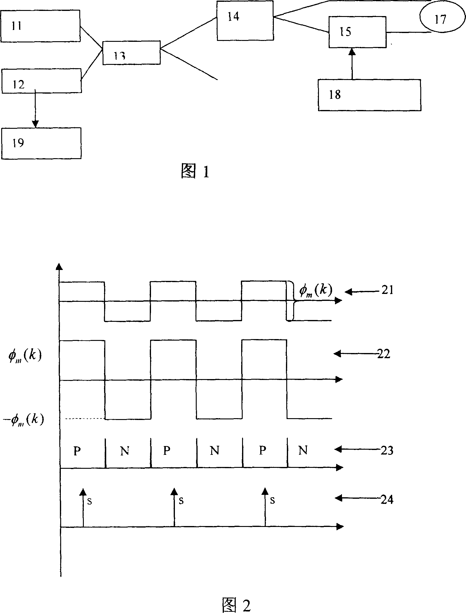
[0044] Figure 1 is a schematic block diagram of a typical test system, in which the light emitted by the light source 11 is divided into two beams by the first beam splitter 13 of the system, one of which reaches the second beam splitter 14 through an optical fiber, and is divided into two , and injected into the two ends of the optical fiber 17, respectively propagating along the clockwise and counterclockwise directions of the optical fiber ring 17, and being modulated by the time delay of the modulator 16 so that there is additionally a modulation depth determined by the modulation waveform, the modulated Waveforms are generated by 18 . The light modulated by the time delay recombines and interferes with each other after propagating separately, and the interference light is reversely split from the beam splitter 14, and part of it reaches the first beam sp...


PUM


Abstract

This invention discloses one light fiber top noise, discrete noise and intensity noise separation method, which comprises the following steps: processing phase modulation on system according to selection phase; high speed digital collection circuit processes sample of output signal in different modulation depth; through sample sequence analyzing getting relative noise even and variance; according to different function, computing three kinds of noise value.

Description

technical field [0001] The invention relates to the field of optical fiber sensing in optoelectronic technology, in particular to a method for separating thermal noise, shot noise and intensity noise of an optical fiber gyroscope. Background technique [0002] The white noise in the fiber optic gyroscope system is the main factor restricting the static accuracy of the system, which is directly expressed as the angle random walk performance index of the fiber optic gyroscope. The size of this indicator directly reflects the quality of the static performance of the system. There are three basic sources of white noise in fiber optic gyroscopes: detector transimpedance thermal noise V themal , shot noise I shotnoise and the intensity noise I RIN , the intensities of these three kinds of white noise can be expressed as: [0003] V themal = 4 kTR * BW <!--img...

Claims


Application Information

Patent Timeline
Patent Type & Authority Applications(China)
IPC IPC(8): G01C19/72H04B10/08H04B10/07
Inventor 刘承陈杏藩舒晓武胡慧珠
Owner ZHEJIANG UNIV
Why Eureka
Try Eureka