
Surface plasmon resonance biosensor using coupled surface plasmons

A surface plasmon and conductive layer technology, applied in biological testing, instruments, scientific instruments, etc., can solve problems such as the decrease of the reflectivity of the conductive layer

Inactive Publication Date: 2007-08-01
AGILENT TECH INC
View PDF0 Cites 6 Cited by
  • Summary
  • Abstract
  • Description
  • Claims
  • Application Information

AI Technical Summary

Problems solved by technology

This causes a sharp drop in the reflectivity of the conductive layer

Method used


Image

  • Surface plasmon resonance biosensor using coupled surface plasmons
  • Surface plasmon resonance biosensor using coupled surface plasmons
  • Surface plasmon resonance biosensor using coupled surface plasmons

Examples


Embodiment Construction

[0016] Reference will now be made in detail to embodiments according to the present invention, examples of which are illustrated in the accompanying drawings, wherein like numerals refer to like elements throughout. Embodiments according to the present invention are described below.

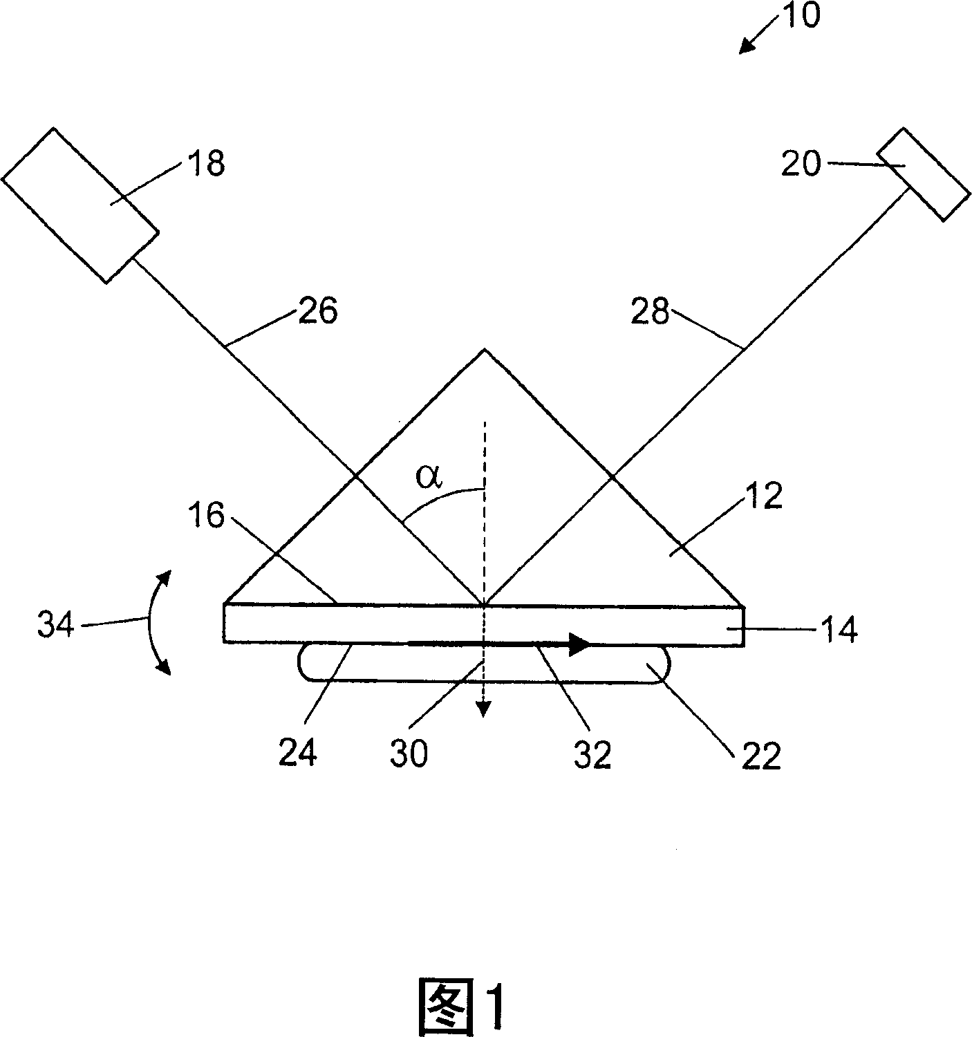
[0017] FIG. 1 shows a surface plasmon resonance biosensor 10 according to the invention comprising a prism 12 , a conductive layer 14 contacting one face 16 of the prism 12 , a light source 18 and a detector 20 . Sample 22 contacts conductive layer 14 and forms conductive layer / sample interface 24 . The light source 18 emits a collimated monochromatic incident light beam 26 having a wavelength λ0. The light source 18 may eg be a laser. An incident light beam 26 enters the prism 12 and is incident on the face 16 of the prism 12 contacting the conductive layer 14 at an angle of incidence α, which is then reflected and forms a reflected light beam 28 which is detected by the detector 20 .

[0018...


PUM

PropertyMeasurementUnit
thicknessaaaaaaaaaa
thicknessaaaaaaaaaa
reflectanceaaaaaaaaaa

Abstract

A surface plasmon resonance apparatus (10) includes a prism (12); a dielectric layer (90) contacting one face (16) of the prism (12); a conducting layer (14) having a first surface contacting the dielectric layer (90) and a second surface to contact a sample (22) to be analyzed by the surface plasmon resonance apparatus (10); and a light source (18) emitting an incident light beam (26) having a wavelength 0 entering the prism (12) and incident on the face (16) of the prism (12) contacted by the dielectric layer (90) at an adjustable incident angle alpha relative to a normal to the face (16) of the prism (12) contacted by the dielectric layer (90). The conducting layer (14) has a thickness that enables generation of slightly asymmetric coupled surface plasmons when the incident angle alpha is equal to a resonance angle determined by the wavelength 0 of the incident light beam (26), an index of refraction (n m ) of the conducting layer, and an index of refraction (n s ) of the sample (22).

Description

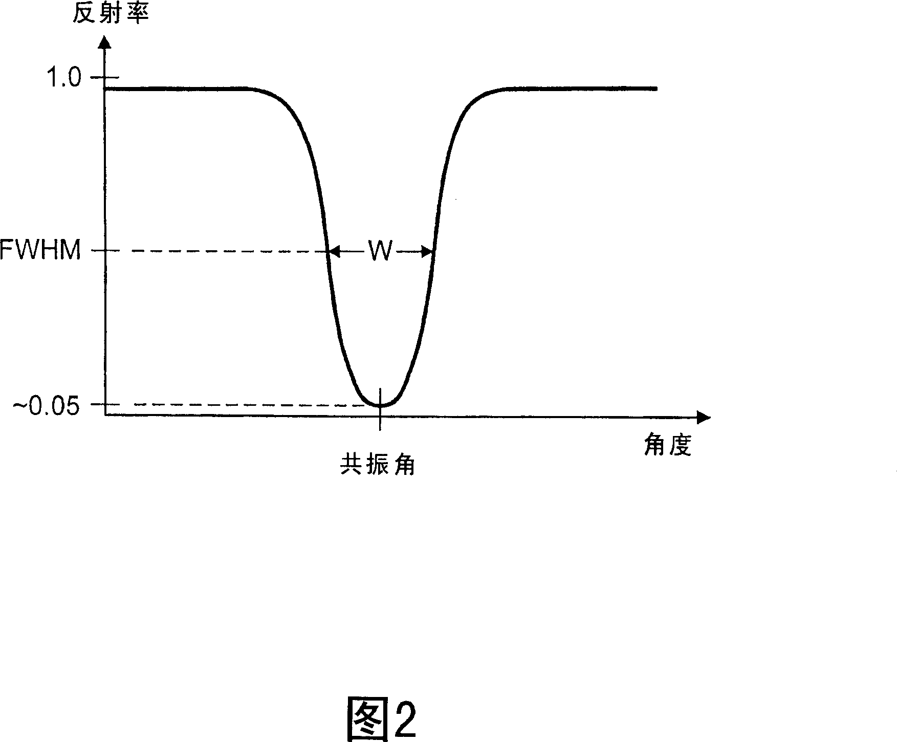
technical field [0001] The present invention relates generally to surface plasmon resonance biosensors (biosensors), and more particularly to surface plasmon resonance biosensors using coupled surface plasmons to reduce the width of reflectivity dips. Background technique [0002] Surface plasmon resonance biosensors detect changes in the sample by detecting changes in the sample's refractive index, thereby not requiring any fluorescence or other labeling of the sample. Therefore, they are called label-free biosensors. [0003] In a typical surface plasmon resonance biosensor, a conductive layer is provided between a prism on one side and a sample on the other. Light of a given wavelength is incident on the conductive layer at a certain angle through the prism. Almost all light will be reflected from the conducting layer except at a certain angle, which depends on the refractive index of the conducting layer and that of the sample. At this angle, known as the resonance an...

Claims


Application Information

Patent Timeline
Patent Type & Authority Applications(China)
IPC IPC(8): G01N21/55G01N33/48G01N21/41
CPCG01N21/553
Inventor 拉塞尔·W·格鲁克
Owner AGILENT TECH INC
Learn More