Eureka AIR delivers breakthrough ideas for toughest innovation challenges, trusted by R&D personnel around the world.

Vibration damping mechanism for bearing

一种振动衰减、轴承的技术,应用在附加机构领域,能够解决难多个突起一致、难刚性设计、制作等问题,达到设计容易、容易性能设计、缓和热膨胀的效果

Active Publication Date: 2007-08-01
KAWASAKI JUKOGYO KK
View PDF1 Cites 33 Cited by
  • Summary
  • Abstract
  • Description
  • Claims
  • Application Information

AI Technical Summary

Problems solved by technology

[0010] According to the disclosed method, compared with the prior art, it can be manufactured at low cost, miniaturized, and the spring constant can be varied in a wide range. However, since the concentric spring is molded by pressing, it is difficult to make multiple The height of each protrusion is consistent with high precision, and it is also difficult to design and manufacture in a manner that maintains arbitrary rigidity.

Method used


Image

  • Vibration damping mechanism for bearing
  • Vibration damping mechanism for bearing
  • Vibration damping mechanism for bearing

Examples


Embodiment 1

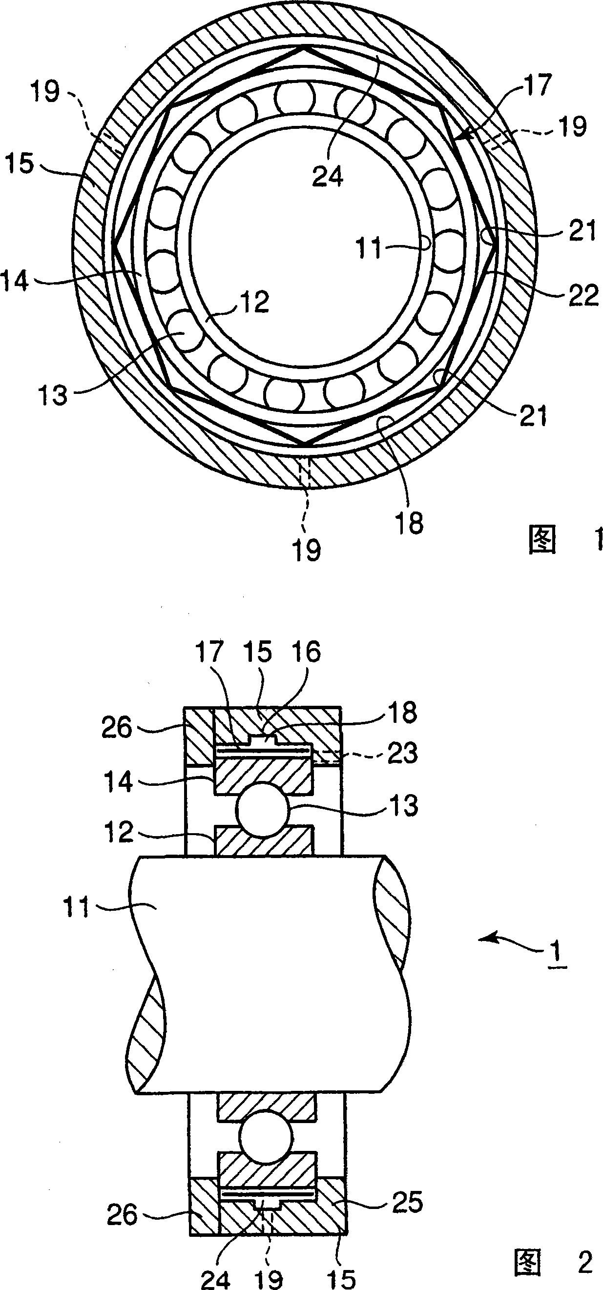
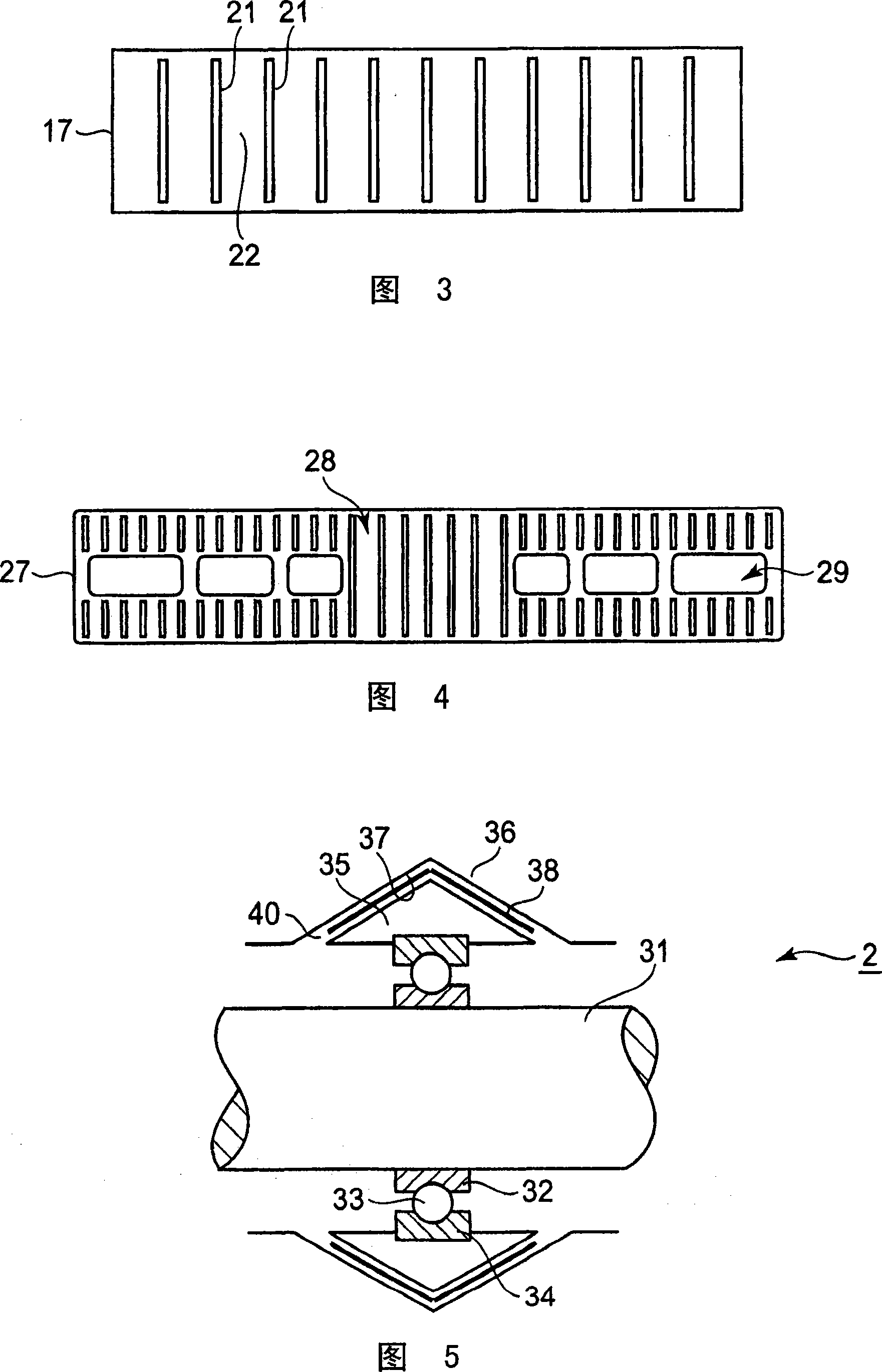
[0042] 1 to 4 are explanatory diagrams of a rolling bearing vibration damping mechanism according to an embodiment of the present invention. Fig. 1 is a plan view of a rolling bearing vibration damping mechanism, Fig. 2 is a side sectional view, Fig. 3 is a plan view of a thin plate spring used therein, and Fig. 4 is a plan view of another thin plate spring.

[0043] The rolling bearing vibration damping mechanism 1 of the present embodiment is a mechanism that performs vibration damping by combining with a rolling bearing, and the rolling bearing is composed of an inner ring 12, a rolling element 13, and an outer ring 14. As shown in Figs. 1 and 2, the rotating shaft 11 is pressed by the inner ring 12, and the outer ring 14 is mounted to the housing 15 via the outer ring 14 of rolling elements 13 such as balls or rollers. on.

[0044]A groove 16 having a diameter slightly larger than the outer circumference of the outer ring 14 is provided on the inner circumference of the housin...

Embodiment 2

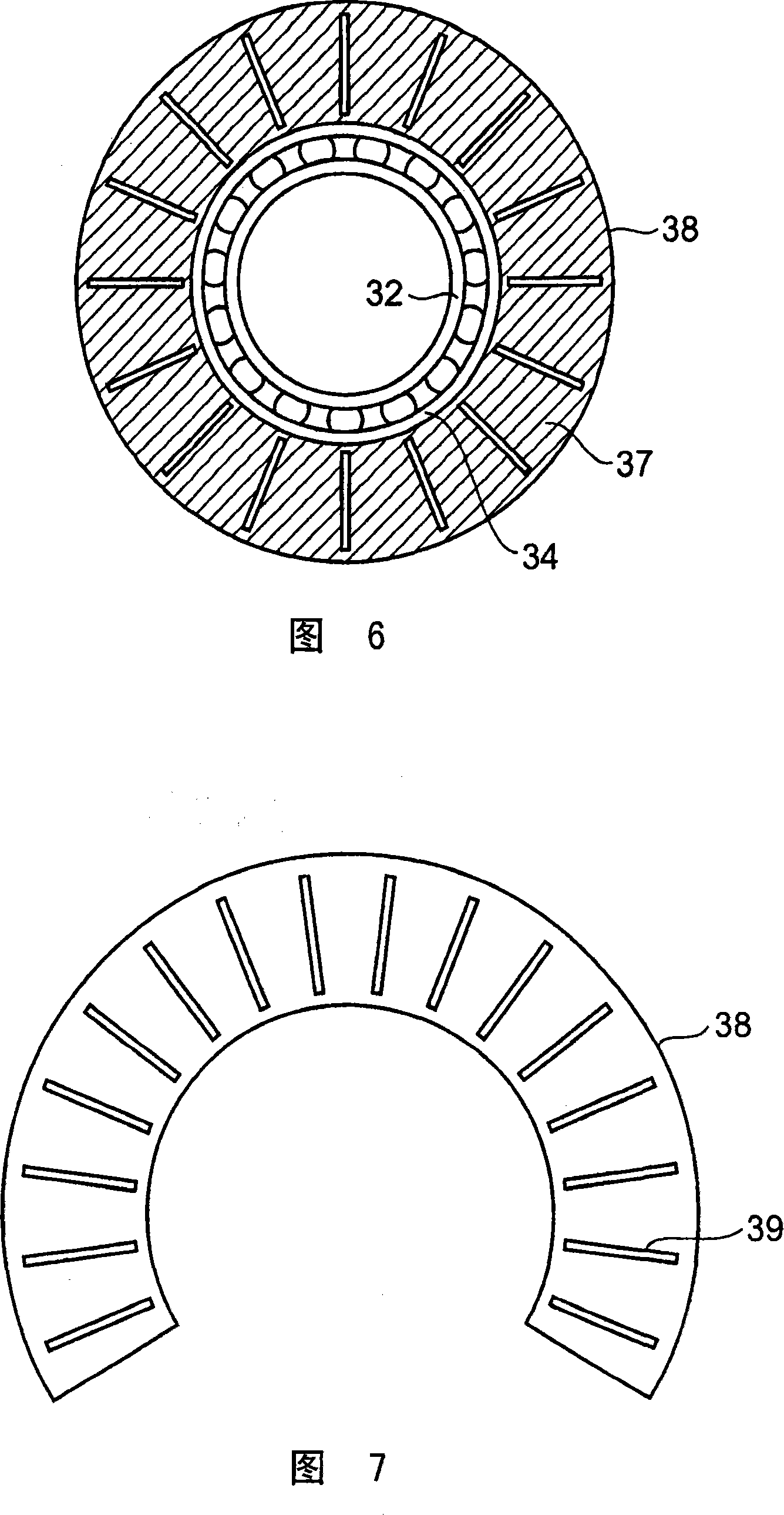
[0063] In the rolling bearing vibration damping mechanism of this embodiment, instead of the accommodating hole of the first embodiment, a ring member having a conical slope is mounted on the outer ring, and the ring member is inserted into an annular groove having a triangular cross section. In the gap between the ring member and the annular groove, a thin plate with a plurality of slits is inserted. In addition, lubricating oil or grease is supplied, and the squeezing film effect caused by the lubricating oil is generated in the gap, thereby It constitutes a squeeze film damper that attenuates vibration.

[0064] In the rolling bearing vibration damping mechanism of this embodiment, the gap between the ring member and the annular groove is inclined with respect to the axial direction of the bearing and the direction perpendicular to the shaft. Therefore, the spring inserted here is relative to the radial and axial direction of the bearing. It has elastic force in both directions...


PUM


Abstract

A squeeze film damper bearing easily manufacturable, having excellent productivity, and reduced in size and a vibration damping mechanism for the rolling bearing capable of having an effect on loads in two of radial and thrust directions. In the vibration damping mechanism (1) for the rolling bearing, a storage hole (16) having a diameter larger than the diameter of the outer periphery (14) of the bearing is formed on the inside of a housing (15) and an oil supply hole (19) supplying an oil into the storage hole is formed in the wall of the housing (15), the bearing is inserted into the storage hole to form an annular clearance (18) on the outer periphery of the bearing, and a thin flat plate (17) having a plurality of slits is inserted into the annular clearance along the circumferential direction. The portions of the thin flat plate held by the slits are formed in an elastic beam to elastically support the bearing at a center position, and the vibration of the bearing is damped by a squeeze film action caused by an oil film generated by supplying the oil into the annular clearance.

Description

Technical field [0001] The present invention relates to a bearing vibration damping mechanism that applies a damping effect to a rolling bearing, and particularly relates to an additional mechanism for easily adjusting the attenuation characteristics of a squeeze film damping bearing. Background technique [0002] Rolling bearings have less friction loss than sliding bearings, so they are used in many machines. However, due to structural reasons, rolling bearings can hardly be expected to effectively dampen vibrations that become a problem when passing at dangerous speeds. Therefore, in order to reduce the mechanical vibration and the dynamic load of the bearing, and to improve the life of the bearing, a damper that adds attenuation to the bearing is used. [0003] Among the dampers used for rolling bearings, there are squeeze film dampers. [0004] The squeeze film damper is suitably used on the outer circumference of the bearing. With the help of the squeeze film produced by th...

Claims


Application Information

Patent Timeline
Patent Type & Authority Applications(China)
IPC IPC(8): F16C27/04F16C19/06F16C27/06F16C33/58F16F1/18F16F15/023F16F15/073
CPCF16C27/045F16F15/0237F16C27/04F16C19/06F16C2300/02F16C27/00
Inventor 和田寿夫阶户秀雄
Owner KAWASAKI JUKOGYO KK
Why Eureka
Eureka Blog
Learn More