

Multi-freedom micro-mechanical arm for minimally invasive operation
A micro-manipulator, minimally invasive surgery technology, applied in manipulators, surgical instruments, operations, etc., can solve problems such as inability to meet laryngeal surgery, and achieve the effects of reliable transmission, enhanced bearing capacity, and increased functions
- Summary
- Abstract
- Description
- Claims
- Application Information
AI Technical Summary
Problems solved by technology
Method used
Image

Examples
Embodiment Construction
[0045] The multi-degree-of-freedom micromanipulator for minimally invasive surgery of the present invention will be described in detail below in conjunction with the embodiments.
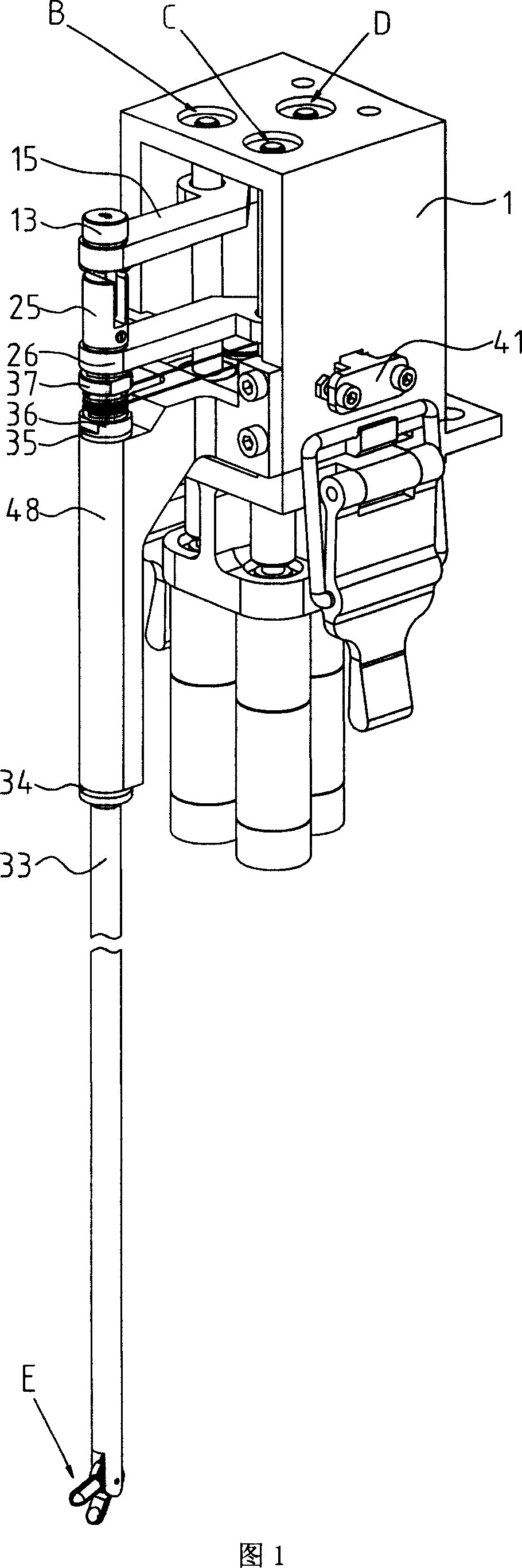
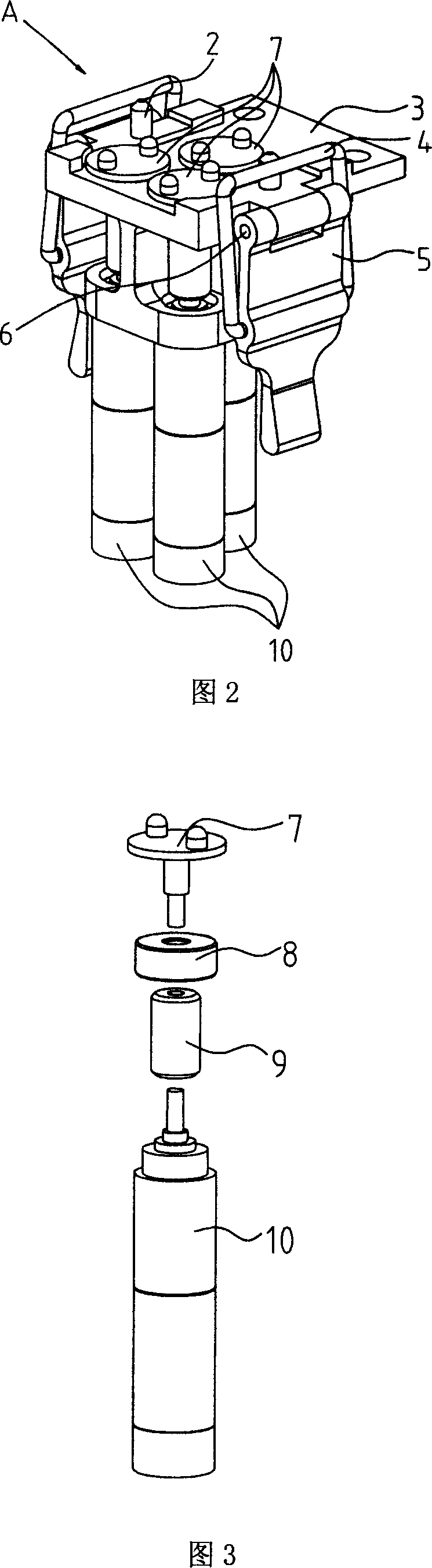
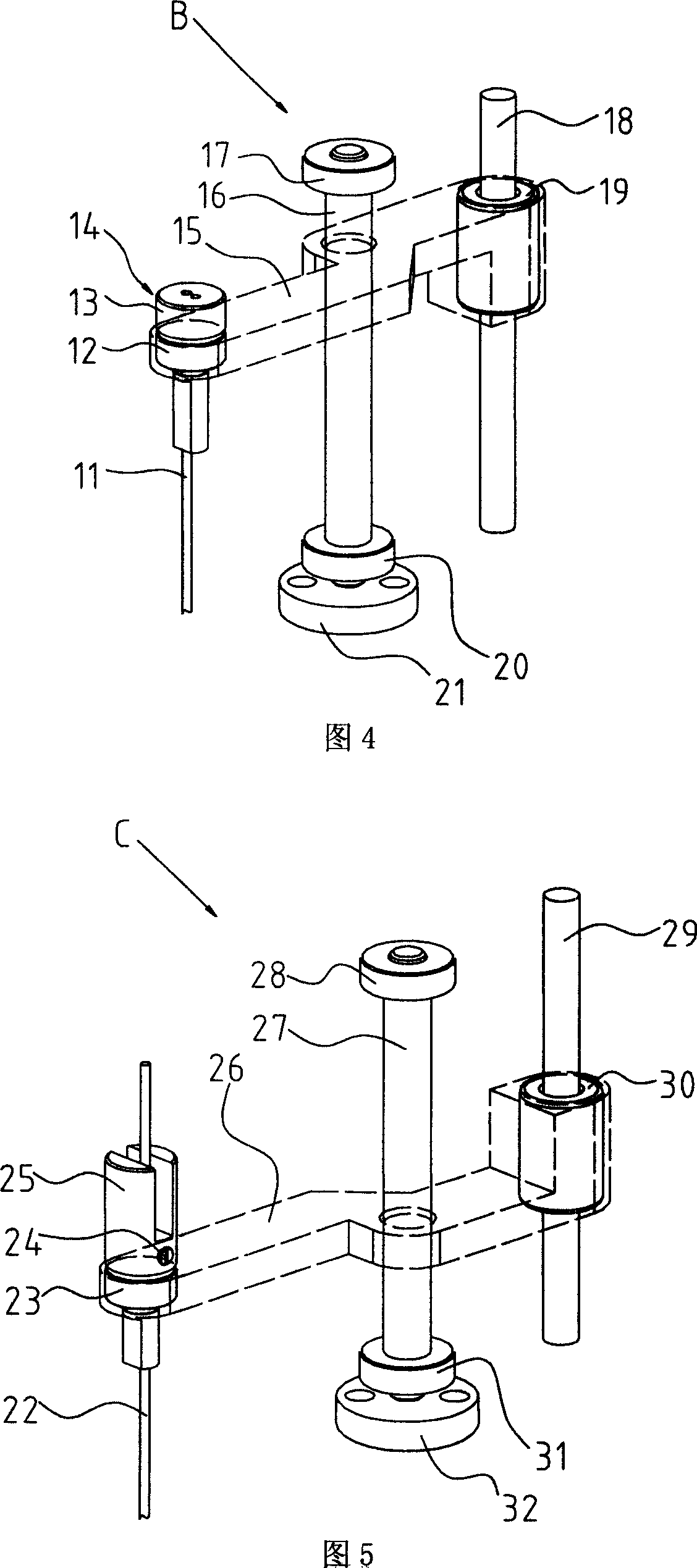
[0046] As shown in Figure 1, Figure 2 and Figure 3, the multi-degree-of-freedom micromanipulator for minimally invasive surgery of the present invention includes a base A, an upper traction mechanism B of the end tool transmission part, and a lower traction mechanism C of the end tool transmission part , the rotation mechanism D of the transmission part of the end tool, the actuator E of the end tool and the transmission box body 1, and in the base A, three sets of servo motors 10 are connected to the three lower clutch discs 7 through three couplings 9 respectively. A lower clutch disc 7 is respectively fixed on the motor frame 3 through three rolling bearings 8; the transmission box body 1 is arranged on the upper surface of the motor frame 3; Inside the box body 1, the upper ends of the upper tra...
PUM
 Abstract
Description
Claims
Application Information