Roadway maintenance vehicle with special power source

A power and source technology, applied in vehicle parts, roads, roads, etc., can solve the problems of reducing the loading of construction materials, shortening the service life, wasting energy, etc., to increase the available space, prolong the service life, and reduce manufacturing costs. Effect

Inactive Publication Date: 2007-08-08
DAGANG HLDG GRP CO LTD
View PDF0 Cites 4 Cited by
  • Summary
  • Abstract
  • Description
  • Claims
  • Application Information

AI Technical Summary

Problems solved by technology

[0003] The above two types of road maintenance vehicles with different traditional power source structures have some disadvantages: the disadvantages of road maintenance vehicles with auxiliary engines are: 1. High equipment manufacturing costs; 2. High pollution, that is, this type of road maintenance vehicles During the construction process, because the automobile engine and the auxiliary engine work together, exhaust gas is emitted into the air at the same time, thereby increasing the pollution to the environment; Larger space and reduced loading of construction materials
And the shortcoming that another class is carried out the road surface maintenance vehicle that divides the force by automobile clutch is: 1, no matter whether working device needs power, as long as the automobile walks, clutch just drives hydraulic pump to work all the time, wasted energy, increased hydraulic pump 2. During the working process of the car, since the power of the working device and the driving device needs to be transmitted through the clutch, the load on the clutch is increased, the wear of the clutch is accelerated, and its service life is shortened.

Method used


Image

  • Roadway maintenance vehicle with special power source
  • Roadway maintenance vehicle with special power source

Examples


Embodiment Construction

[0009] Describe an embodiment of the present invention below in conjunction with accompanying drawing:

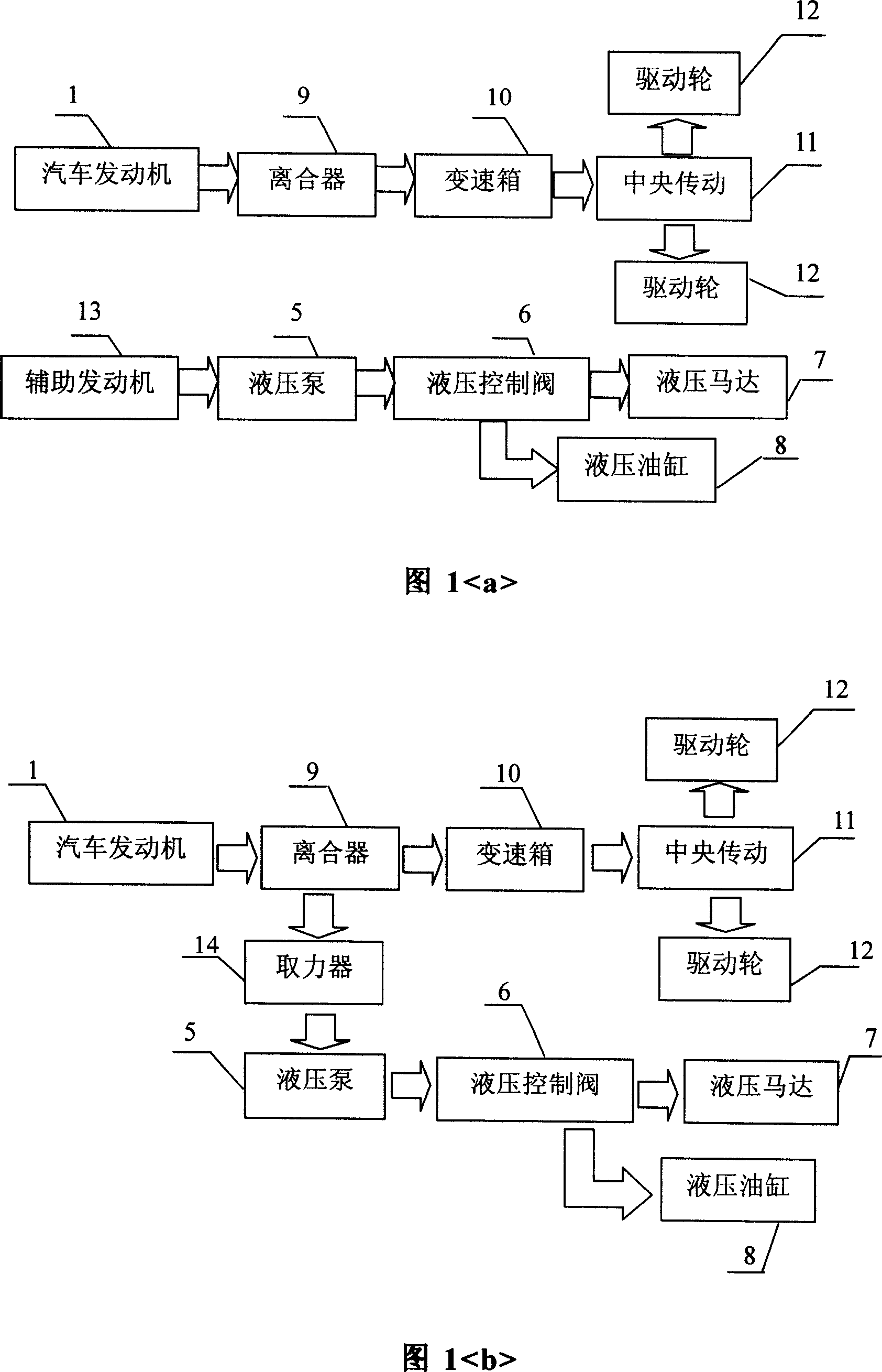
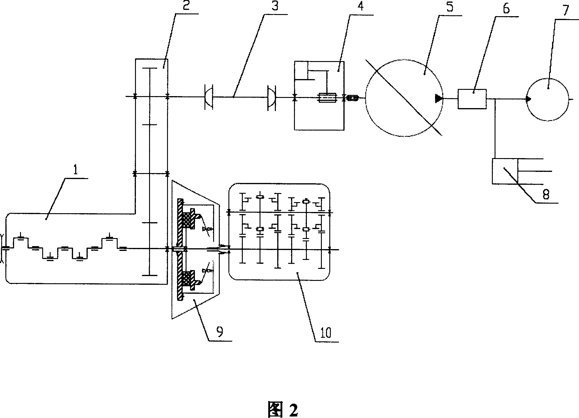
[0010] Fig. 2 is a schematic diagram of the power plant structure of the road surface maintenance vehicle of the present invention, which mainly includes an automobile engine 1, an engine power take-off flange 2, a drive shaft 3, a separator 4, a hydraulic pump 5, a hydraulic control valve 6, a hydraulic motor 7, a hydraulic Oil cylinder 8, clutch 9, gearbox 10.

[0011] On the front end of the engine crankshaft between the automobile engine 1 and the clutch 9, a power take-off flange 2 is fixed; one end of the transmission shaft 3 is connected to the power take-off flange 2 through a universal joint, and the other end is connected to the separator 4; The other end of the separator 4 drives the hydraulic pump 5 to work through the spline shaft.

[0012] In this embodiment, a part of the power output from the automobile engine is transmitted to the clutch 9 through ...


PUM


Abstract

A specially powered road maintenance vehicle with all the power coming from the engine has engine crankshaft front end between the engine and clutch, engine power fetching flange fixed and connected with the drive shaft, whose the other end connected with the separator and the separator connected with the hydraulic pump. The device reduces the equipment manufacturing cost, increasing applicable space, with reduced energy, reduced noise, extended durability of equipment.

Description

technical field [0001] The invention belongs to the power technology of vehicle-mounted road maintenance vehicles. Background technique [0002] Traditional pavement maintenance vehicles generally have two types of power sources for their work: one type, such as slurry sealing vehicles and some synchronous sealing vehicles, requires power from the vehicle's own engine and auxiliary engine (see figure 1 shown): the automobile engine 1 is responsible for the running function, and the automobile engine transmits power to the gearbox 10 through the clutch 9, and the gearbox 10 drives the central transmission 11 to drive the automobile driving wheel 12, so that the automobile completes the task of traveling; the auxiliary engine 13 then Provide the power of the working device of the vehicle, that is, the auxiliary engine drives the hydraulic pump 5, and then drives the hydraulic cylinder 8 and the hydraulic motor 7 through the hydraulic control valve 6 to complete the work task....

Claims


Application Information

Patent Timeline
Patent Type & Authority Applications(China)
IPC IPC(8): B60K25/02E01C19/26
Inventor 李太杰
Owner DAGANG HLDG GRP CO LTD
Why Eureka
Try Eureka