Energy-saving electric-hydraulic variable-valve control system

A valve control system, electro-hydraulic technology, applied in the direction of non-mechanical actuated valves, engine components, machines/engines, etc., can solve the problems of high energy consumption, high cost, high system cost, etc., to reduce input current and energy consumption Consumption, improve the effect of response speed

Inactive Publication Date: 2007-08-08
ZHEJIANG UNIV +1
View PDF0 Cites 7 Cited by
  • Summary
  • Abstract
  • Description
  • Claims
  • Application Information

AI Technical Summary

Problems solved by technology

While bringing convenience to people, it also poses a serious problem: high energy consumption and high pollution
The camless driving mechanism can be divided into electromagnetic type and electro-hydraulic type. The electromagnetic type uses a pair of electromagnets with springs. In order to improve the frequency response of the system, the vehicle voltage needs to be greatly increased, which brings safety. At the same time, the valve seating buffer cannot be realized, and the vibration is large, which affects the life of the engine
In order to realize the valve lift closed-loop control, high-frequency precision displacement sensors and high-power electronic control devices are required, so the high cost of the system will inevitably affect market promotion.
Electro-hydraulic variable valve technology is divided into servo control, proportional control, and switch control. The variable valve technology of electro-hydraulic servo control was first realized in the laboratory, but it has been eliminated by the industry due to its high cost.

Method used


Image

  • Energy-saving electric-hydraulic variable-valve control system

Examples


Embodiment Construction

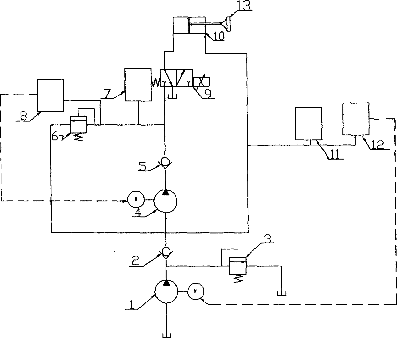
[0010] As shown in the accompanying drawings, an energy-saving electro-hydraulic variable valve control system of the present invention can realize the recovery and reuse of system energy. The system includes a first quantitative pump 1 , a second quantitative pump 4 , a high-pressure energy storage device 7 , a low-pressure energy storage device 11 , a high-speed switching valve 9 , a hydraulic actuator 10 and a valve 13 . The outlet of the first quantitative pump 1 is connected to the inlet of the first safety valve 3 and the inlet of the first one-way valve 2 at the same time, the outlet of the first safety valve 3 is connected to the oil tank, and the inlet of the second quantitative pump 4 is connected to the inlet of the second safety valve 6 at the same time. The outlet of the low-pressure energy storage device 11, the inlet of the first pressure detection device 12 and the right chamber of the hydraulic cylinder of the hydraulic actuator 10 are connected, and the outlet...


PUM


Abstract

The invention discloses a control system for an energy saving electro-hydraulic air-changeable door, which can realize the recovery of energy and recycle, comprises constant pump, one-way valve, safe valve, energy storage device, hydraulic actuator, air door, pressure test device and high-speed switch valve. The hydraulic actuator comprises oil cylinder, piston and piston bar. The constant pump inputs energy to the energy storage device. The one-way valve between the energy storage device and the hydraulic pump can prevent the pressure oil in the energy storage device returning. The high-pressure energy storage device is connected with the pressure port of three-way high-speed switch valve and the left cavity of cylinder is connected with the control port of high-speed switch valve. When the right cavity of cylinder is not connected with the oil return port of high-speed switch valve, the oil return port of high-speed switch valve is connected with the oil tank. The energy storage device provides energy to the hydraulic actuator. As the pressure test device measures the pressure value at the outlet of energy storage device, energy is filled in the energy storage device in time so as to decrease the energy consumption of system greatly.

Description

technical field [0001] The invention relates to an internal combustion engine valve control system, in particular to an energy-saving electro-hydraulic variable valve control system. Background technique [0002] With the improvement of people's quality of life, automobiles have become a common means of transportation in people's daily life. While bringing convenience to people, it also raises a serious problem: high energy consumption and high pollution. The power source of the car is the engine, and the engine is a machine that converts a certain form of energy into mechanical energy. Most of the engines used in modern automobiles are internal combustion engines, which are machines that convert the chemical energy of fuel combustion into thermal energy, and then convert the thermal energy into mechanical energy. To complete this energy conversion process, it generally needs to go through four processes of intake, compression, work, and exhaust. The intake and exhaust pro...

Claims


Application Information

Patent Timeline
Patent Type & Authority Applications(China)
IPC IPC(8): F01L9/02F01L9/10
Inventor 金波谢英俊翁振涛刘金榕凌俊杰
Owner ZHEJIANG UNIV
Why Eureka
Try Eureka