Movable combination valve

A compound valve and movable connection technology, which is applied in the field of compound valves, can solve the problems of inaccurate ball seal positioning, difficult processing, and difficult control of welding quality, and achieve the effect of accurate ball seal position and simple machining

Inactive Publication Date: 2007-08-08
ZHUZHOU HONGYUAN HIGH PRESSURE VALVE
View PDF0 Cites 5 Cited by
  • Summary
  • Abstract
  • Description
  • Claims
  • Application Information

AI Technical Summary

Problems solved by technology

The welded valve seat has the following disadvantages: 1. Due to the deep packing hole, machining is more difficult, especially for small-diameter DN10, DN15, DN20 and other valves with small apertures, and the processing is more difficult; 2. The welding quality is difficult to control, especially the clamping Ballast, air holes, and cracks are not easy to be found in time during welding, resulting in reverse work and low product qualification rate; 3. Due to the action of welding stress, it is difficult to guarantee 100% no cracks even if it is tempered in time. The STL alloy material commonly used at home and abroad It is difficult to control the welding quality; 4. Due to the irregularity of the valve body, the deformation is large under high temperature conditions, and the design roundness and ovality of the valve seat cannot be guaranteed, resulting in the valve not being sealed; 5. The welded valve seat used is in the system, there is no Those that are not washed out, especially the traditional single-stem and seat valves, are more severely washed out. If the washout is slight, the equipment can be repaired on site. If the washout is severe, the valve must be cut off and re-welded, and cannot be replaced on site.
[0004] Currently used compound valves usually use two pairs of gears to achieve two actions. When the ball seal is closed, the sector gear cannot be completely disengaged, resulting in inaccurate positioning of the ball seal and a large positioning error of the pull rod, which is very easy to get stuck. I can't pull it out, so I can't realize the action at all.

Method used


Image

  • Movable combination valve

Examples


Embodiment Construction

[0010] The specific embodiments of the present invention will be described in detail below in conjunction with the accompanying drawings.

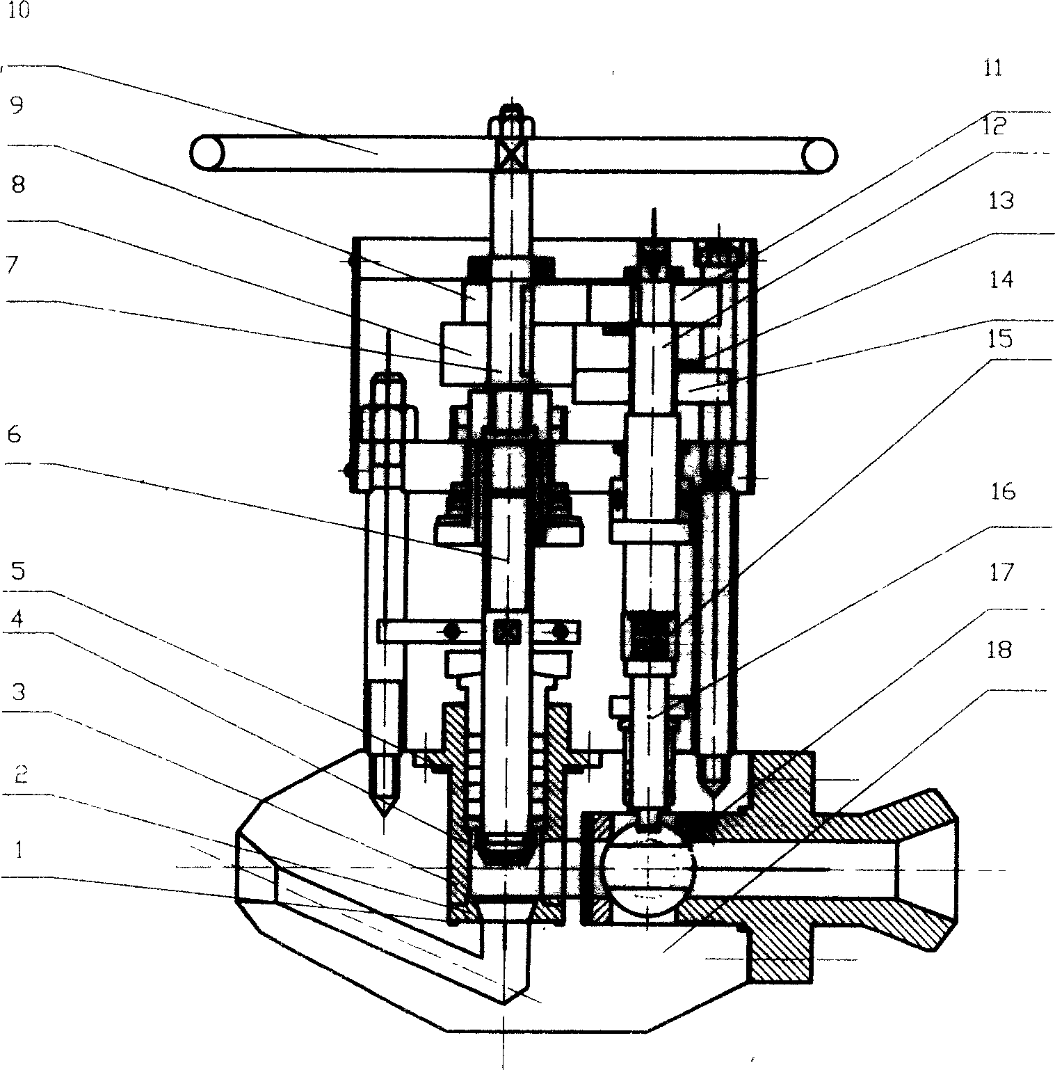
[0011] The technical scheme of the present invention is realized through the following approach, it is made up of globe valve and ball valve, and globe valve comprises valve body 18, valve seat 2, valve stem, cage 3, valve core 4, wherein cage 3 and valve seat 2 For movable connection, the valve seat 2 and the valve body 18 are also movable connected, the cage 3 is provided with a packing hole, the valve core 4 is a movable valve core; the valve stem is composed of a lower cut-off valve stem 6 and an upper cut-off valve stem 7, and There is a spline connection between the lower cut-off valve stem 6 and the upper cut-off valve stem 7; the upper cut-off valve stem 7 is fixed with a driving gear 8 and a driving cam 9, and the driving cam 9 is located above the driving gear 8;

[0012] The ball valve includes a sphere 17, a lower ball valve st...


PUM


Abstract

The invention relates to a movable composite valve formed by a stop valve and a ball valve, wherein, the cage sheath of stop valve is movably connected to the valve base; the valve base is movably connected with the valve body; the cage sheath has stuff holes; the valve element is movable; the valve rod is formed by lower stop valve rod and upper stop valve rod connected with spline; the upper stop valve rod is fixed with an active gear and an active cam while the active cam is above the active gear; the lower ball valve rod and upper ball valve rod of ball valve are connected via the connecting sheath; the upper valve rod is fixed with an inactive cam above the inactive gear; the inactive cam and the inactive gear are arranged with a clutch; the inactive gear is connected with the screw of upper ball valve rod; the active gear of stop valve is meshed with the inactive gear of ball valve; the active cam of stop valve is meshed with the inactive cam of ball valve. The cage sheath and the valve base are separated, with controlled quality and repaired property on site. And the invention uses cam device to improve the accuracy of seal position of ball.

Description

technical field [0001] The invention relates to a compound valve, in particular to a movable compound valve. Background technique [0002] In the high-temperature and high-pressure systems of electric power, petroleum, chemical industry and other industries, high-temperature and high-pressure valves are usually used in large quantities. Due to the harsh working conditions of the system, internal leakage of the valve often occurs in a short period of time or in the case of very few operations. Once the valve Internal leakage, due to the scouring effect, the valve will fail quickly, which will bring huge energy waste and economic loss to the user. As we all know, the cut-off valve is mainly cut off by the sealing of the valve core and the valve seat. One side of the composite valve is a cut-off valve and the other is a ball valve. [0003] The tightness of the block valve is mainly determined by the structure of the valve seat. From the perspective of domestic and foreign va...

Claims


Application Information

Patent Timeline
Patent Type & Authority Applications(China)
IPC IPC(8): F16K99/00F16K1/00F16K5/16F16K31/44
Inventor 孔华山张湘泉袁军
Owner ZHUZHOU HONGYUAN HIGH PRESSURE VALVE
Why Eureka
Try Eureka