Permanent magnet system for rotary magnetic refrigeration apparatus

A magnetic refrigeration and magnet technology, which is used in refrigerators, refrigeration and liquefaction, lighting and heating equipment, etc., can solve the problems of high energy consumption, large unilateral magnetic pull, damaged shafts and bearings, etc., and achieves high operational reliability. The effect of low vibration and noise and high magnetizing field strength

Inactive Publication Date: 2007-08-08
INST OF ELECTRICAL ENG CHINESE ACAD OF SCI
View PDF0 Cites 25 Cited by
  • Summary
  • Abstract
  • Description
  • Claims
  • Application Information

AI Technical Summary

Problems solved by technology

[0002] At present, traditional gas compression refrigeration technology is widely used in household appliances, industrial production, aerospace and other fields to refrigerate, but there are two major defects in this technology: First, the gas refrigeration technology uses compressors to cause low efficiency and low energy consumption. Second, compression refrigeration uses gaseous working fluids such as freon and ammonia, which cause pollution and damage to the environment, especially freon, which causes the destruction of the atmospheric ozone layer and has seriously threatened human survival and safety.
Although the permanent magnet of this structure can produce a higher-intensity magnetic field, it has two disadvantages: one is that most of the runner is located outside the permanent magnet, and this rotating part is not closed, which will give the magnet The structural design of the refrigerator causes difficulties; the second is that only a part of the circumference of the runner is in the magnetic field of the permanent magnet, which will generate a very large unilateral magnetic pull on the runner
This one-sided magnetic pull can cause vibration of the rotor as it spins, and can even damage the shaft and bearings

Method used


Image

  • Permanent magnet system for rotary magnetic refrigeration apparatus

Examples


Embodiment Construction

[0017] The present invention will be further described below in conjunction with the accompanying drawings and specific embodiments.

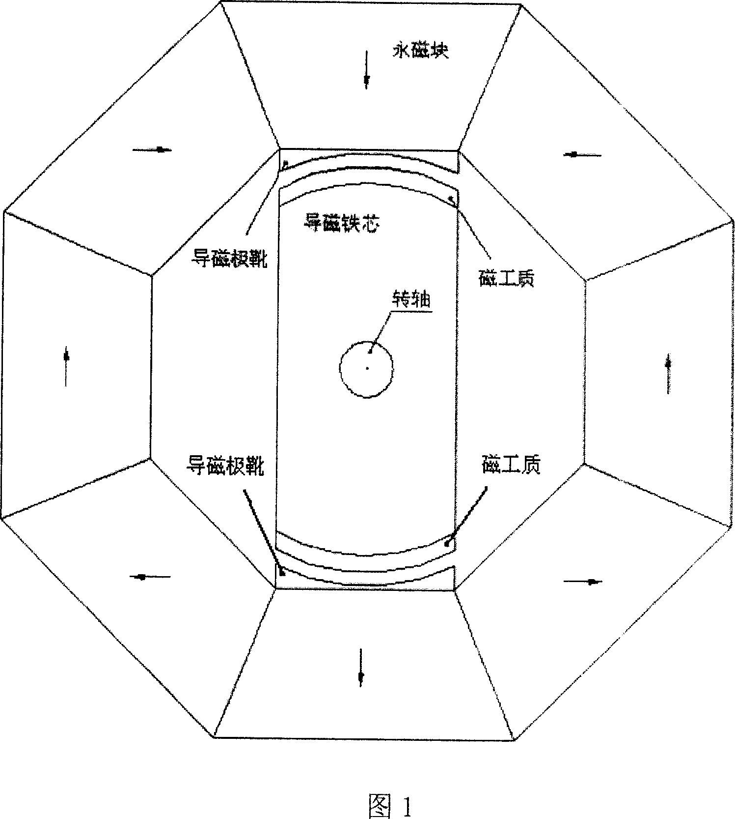
[0018] As shown in Figure 1, the Halbach hollow cylindrical permanent magnet in the stator is composed of 8 trapezoidal permanent magnets, and its magnetization direction is determined by Halbach's rotation theorem, as shown by the arrow in Figure 1. The magnetically conductive pole piece is shaped like an arch bridge, one side of which is consistent with the inner cavity wall of the permanent magnet, and the other side is arc-shaped. The magnetically conductive pole pieces are respectively located under and above the upper and lower permanent magnet blocks magnetized in the radial direction, and are closely attached to the inner cavity walls of the centers of the N and S poles of the permanent magnets. at the geometric center of the stator.

[0019] The axis of the rotor is located at the center of the rotor, and its center coincides with the...


PUM


Abstract

The invention relates to a permanent magnet system used in rotary magnetic refrigerator, wherein, the stator comprises a hollow cylinder permanent magnet and a magnetic conductive polar shoe; the hollow cylinder magnet is assembled symmetry around the central axle of the section of magnet via even permanent magnets; the magnetic direction of permanent magnet is decided by Halbach rotation theory; the magnetic conductive polar shoes are formed by two metals with better magnetic conductivity, while one side face is engaged with the wall of the chamber of permanent magnet, while another side is arc; two magnetic conductive polar shoes are contacted on the wall of chamber at the center of N and S polarities, with 180 degree spatial difference. The rotor comprises a rotary axle, a magnetic conductive iron corn and a magnetic medium; the rotary is cylinder; the iron corn is made from magnetic conductive magnet, as the cylinder with central hole or with cut-off two edges, sheathing the rotary axle while the rotary axle is at the center; two magnetic mediums are mounted on two outer arc faces of magnetic conductive iron corn, while the spatial positions are 180 degree different. The invention can be used as rotational permanent magnetic device.

Description

technical field [0001] The present invention relates to a permanent magnet system, in particular to a permanent magnet system for rotating magnetic refrigeration equipment. Background technique [0002] At present, traditional gas compression refrigeration technology is widely used in household appliances, industrial production, aerospace and other fields to refrigerate, but there are two major defects in this technology: First, the gas refrigeration technology uses compressors to cause low efficiency and low energy consumption. Second, compression refrigeration uses gaseous working fluids such as freon and ammonia, which cause pollution and damage to the environment, especially freon, which causes the destruction of the atmospheric ozone layer and has seriously threatened human survival and safety. In order to solve the above-mentioned environmental pollution problems, people are actively developing Freon-free working fluids that do not destroy the ozone layer of the atmosp...

Claims


Application Information

Patent Timeline
Patent Type & Authority Applications(China)
IPC IPC(8): F25B21/00H01F7/02
CPCY02B30/66Y02B30/00
Inventor 夏东
Owner INST OF ELECTRICAL ENG CHINESE ACAD OF SCI
Why Eureka
Try Eureka