
Rotary clutch

A clutch and rotary technology, applied in the direction of high-voltage air circuit breakers, electrical components, electric switches, etc., can solve the problems of reducing the reliability of the spring operating mechanism and fatigue-resistant operation life, and the reliability, stability and durability of the clutch action. The effect of simple structure, strong adaptability, and stable and reliable action can be achieved

Inactive Publication Date: 2007-08-08
冯保明 +2
View PDF0 Cites 5 Cited by
  • Summary
  • Abstract
  • Description
  • Claims
  • Application Information

AI Technical Summary

Problems solved by technology

[0002] At present, in the spring operating mechanisms of various medium and low voltage load switches and circuit breakers at home and abroad, the clutch and protection of the operating force, spring energy storage, and closing action are all controlled in the form of friction lock; due to the friction lock form The friction of the locking point is very large and easy to wear, which has a relatively large negative impact on the reliability, stability, and durability of the clutch action. This friction locking form is now widely used in various types of spring operating mechanisms. Thereby reducing the reliability of the action of the spring operating mechanism and the fatigue life of the operation

Method used


Image

  • Rotary clutch
  • Rotary clutch
  • Rotary clutch

Examples


Embodiment Construction

[0020] The present invention will be further described in detail below in conjunction with the accompanying drawings and embodiments.

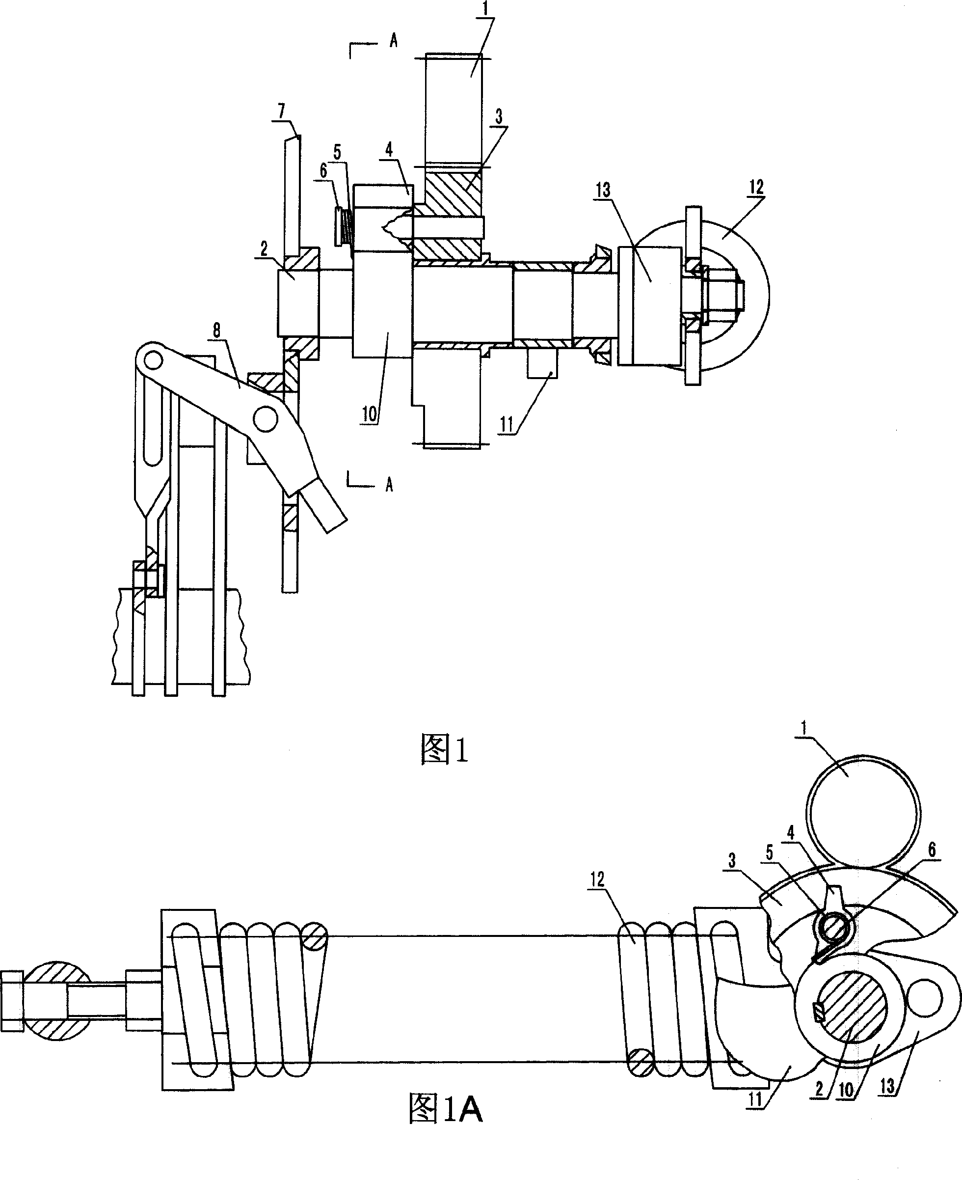
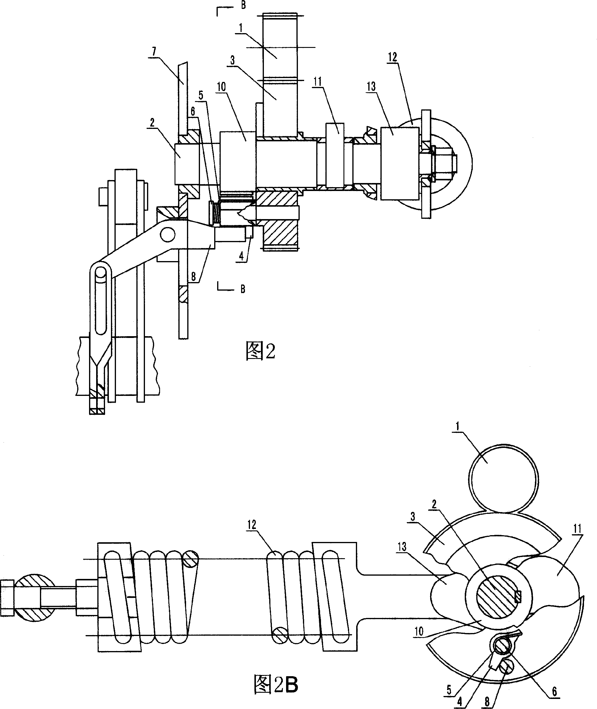
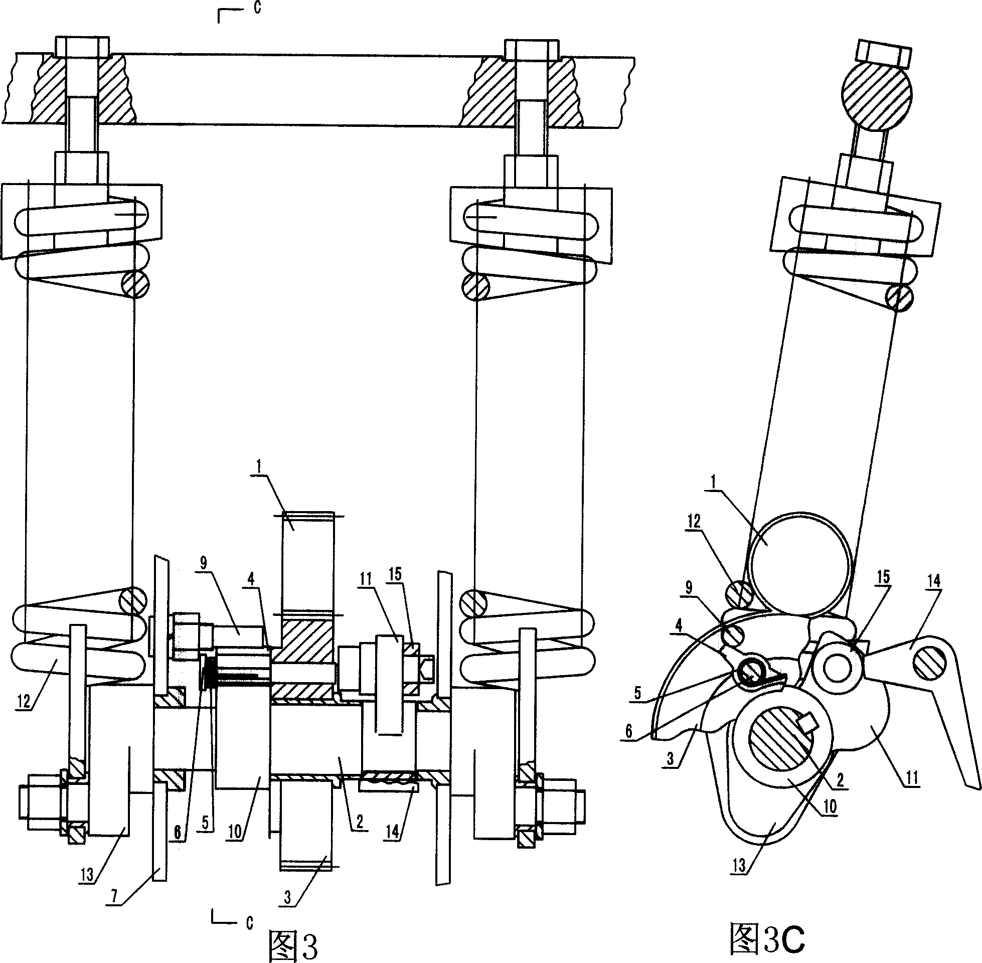
[0021] 1 to 4D are structural schematic diagrams of a rotary clutch. The rotary clutch includes a small gear 1, a main shaft 2 and a large gear 3. The main shaft 2 is equipped with a large gear 3, and the large gear 3 meshes with the pinion 1. The pin shaft 6 of the spring 5 is fixed with a convex sleeve 10 on the main shaft 2 corresponding to the top block 4, and the convex sleeve 10 is shaped on a convex shoulder to match the end of the top block 4; a cam 11 is fixed in the middle of the main shaft 2, and the main shaft 2 The end is fixed with the energy storage crank arm 13 that pulls the energy storage spring 12 and rotates synchronously with the main shaft 2; the side plate 7 is provided with a contact block with energy storage and closing self-locking protection functions.

[0022] One is that as shown in Figures 1 to 2B, the stopper is...


PUM


Abstract

The invention discloses one rotation clutch, which comprises small gear and main axis and large gear, wherein, the main axis matches large gear and the large gear meshes with small one. The actions comprise the following steps: large gear end is fixed with top block and torque bolt; the main axis relative to top block is fixed with protruding cover to process protruding shoulder and top block; the main axis is fixed with protruding wheel and one pulling memory spring arm; the side board is set with memory and clutch automatic protection block part.

Description

technical field [0001] The invention relates to the field of medium and low voltage switches, in particular to a rotary clutch. It can be adapted to spring operating mechanisms of various medium and low voltage load switches and circuit breakers, and is used as clutch and protection for operating force, spring energy storage, and closing action. Background technique [0002] At present, in the spring operating mechanisms of various medium and low voltage load switches and circuit breakers at home and abroad, the clutch and protection of the operating force, spring energy storage, and closing action are all controlled in the form of friction lock; due to the friction lock form The friction of the locking point is very large and easy to wear, which has a relatively large negative impact on the reliability, stability, and durability of the clutch action. This friction locking form is now widely used in various types of spring operating mechanisms. The reliability of the action...

Claims


Application Information

Patent Timeline
IPC IPC(8): H01H3/30H01H33/40H01H71/10H01H71/50
Inventor 冯保明
Owner 冯保明
Learn More