Electrical spindle drived by AC permanent magnet synchronous motor

A permanent magnet synchronous motor and electric spindle technology, which is applied to synchronous motors with stationary armatures and rotating magnets, synchronous machine parts, electric components, etc., can solve the high technical requirements for motor rotor and stator cooling and affect the reliability of machine tools To solve the problems of safety and stability, large size of AC permanent magnet asynchronous motor, etc., to achieve the effect of good control characteristics, small torque fluctuation and easy cooling

Inactive Publication Date: 2007-08-08
DALIAN GUANGYANG SCI & TECH ENG CO LTD
View PDF0 Cites 4 Cited by
  • Summary
  • Abstract
  • Description
  • Claims
  • Application Information

AI Technical Summary

Problems solved by technology

[0003] In view of the above problems, the present invention provides an electric spindle driven by an AC permanent magnet synchronous motor. Problems that affect the reliability and stability of the machine tool under poor conditions

Method used


Image

  • Electrical spindle drived by AC permanent magnet synchronous motor

Examples


Embodiment Construction

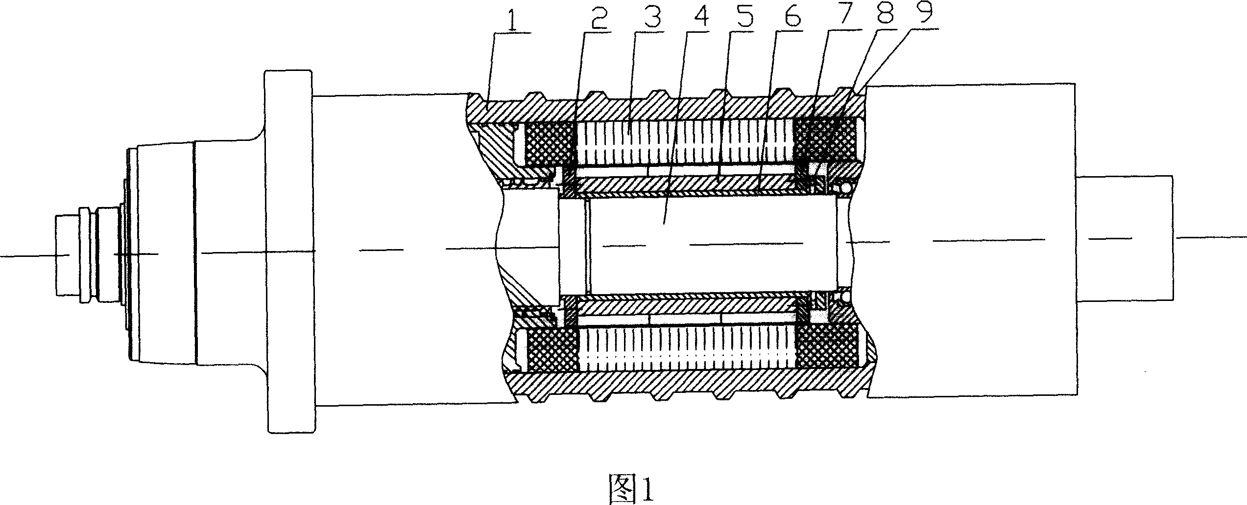
[0010] Referring to Fig. 1, the subsection diagram of the partial structure of the built-in electric spindle adopting the permanent magnet synchronous motor is illustrated. Wherein, the motor stator 3 is located outside the rotor 5 , end covers 2 and 7 are provided at both ends of the rotor, and an inner sleeve 6 is provided between the rotor 5 and the core shaft 4 of the electric spindle. The mandrel 4 is connected to the inside of the inner sleeve 6 in an interference manner, and the inner sleeve 6 is also connected to the interior of the rotor 5 in an interference manner. Also shown among the figure is an oil inlet hole 8 for dismounting.

[0011] Usually, both ends of the motor of the electric spindle are equipped with spindle bearings, and the heating of the motor will directly reduce the working accuracy of the bearings. If the heat dissipation of the motor is not solved well, it will affect the reliability and stability of the machine tool. However, for synchronous mot...


PUM


Abstract

The invention discloses one electrical axis driven by alternating permanent simultaneous motor, which comprises outer ring stator and inner ring rotor, wherein, the rotor inside is fixed with electrical axis core; the stator outer ring is covered with cooling cover with spiral tank. The invention is of high efficiency, low noise, reliable operation and small torque.

Description

technical field [0001] The present invention relates to an electric spindle, more specifically, relates to an electric spindle adopting AC permanent magnet synchronous technology. Background technique [0002] The built-in electric spindle is a technology in which the motor and the spindle are integrated. The rotor of the motor is the rotating part of the spindle. At present, some electric spindles use AC permanent magnet asynchronous motors. The problem is that AC permanent magnet asynchronous motors are large in size and poor in dynamic balance. Both the rotor and stator of the motor need to be cooled, which requires high cooling technology. Since the two ends of the motor of the electric spindle are the spindle bearings, the heating of the motor will directly reduce the working accuracy of the bearings. If the heat dissipation of the motor is not solved well, it will affect the reliability and stability of the machine tool. Contents of the invention [0003] In view of...

Claims


Application Information

Patent Timeline
Patent Type & Authority Applications(China)
IPC IPC(8): H02K21/14H02K21/02H02K7/00H02K5/20
Inventor 于德海张文峰郑君民王庆鹏李文庆冯兆冰陈伟华张可畏阮叁芽
Owner DALIAN GUANGYANG SCI & TECH ENG CO LTD
Why Eureka
Try Eureka