Minimally Invasive lumbar fusion device and its use method

An intervertebral fusion device and fusion device technology, applied in the field of medical devices, can solve problems such as stress reduction, unsatisfactory bone induction effect, and nerve damage, and achieve the goal of restoring the height of the intervertebral space, reducing human injury, and reducing stress concentration. Effect

Inactive Publication Date: 2007-08-15
王建华
View PDF0 Cites 7 Cited by
  • Summary
  • Abstract
  • Description
  • Claims
  • Application Information

AI Technical Summary

Problems solved by technology

[0003]1. On the one hand, in order to ensure the strength of the intervertebral cage and the full contact with the endplate, it is hoped that the cage has a relatively large size. On the other hand, When the intervertebral space becomes narrow due to intervertebral disc degeneration, it is difficult to insert the intervertebral cage into the intervertebral space. It is often necessary to contact the spreader to stretch the intervertebral space, so that the endplate contact surface of the intervertebral cage is along the direction of the vertebral endplate. Insertion, when implanting a large-sized intervertebral fusion device, it is necessary to open a large inner window, which is likely to cause damage to the nerves, and minimally invasive surgery cannot be achieved. However, the structure and insertion method of the existing intervertebral fusion device requires The configuration is complex with the help of special tools such as spreaders
[0004]2. In order to improve the fusion effect of the intervertebral fusion device as much as possible, there is a storage warehouse inside the intervertebral fusion. Fill the intervertebral fusion device with biologically active substances, then push the intervertebral fusion device into the intervertebral space, and promote the healing of the bone graft in the intervertebral space by opening a storage compartment in the intervertebral fusion device; because the intervertebral fusion device and the endplate The contact between the endplates is through the contact surface. In order to guide the bone to the contact surface, a large through hole is provided on the endplate contact surface, but this will undoubtedly reduce t

Method used


Image

  • Minimally Invasive lumbar fusion device and its use method
  • Minimally Invasive lumbar fusion device and its use method
  • Minimally Invasive lumbar fusion device and its use method

Examples


Embodiment Construction

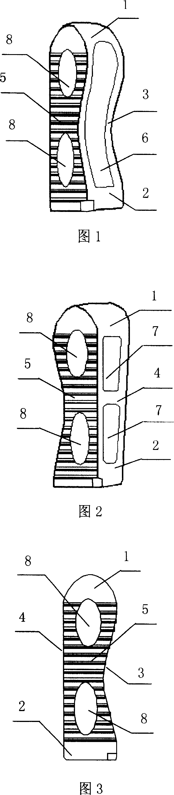
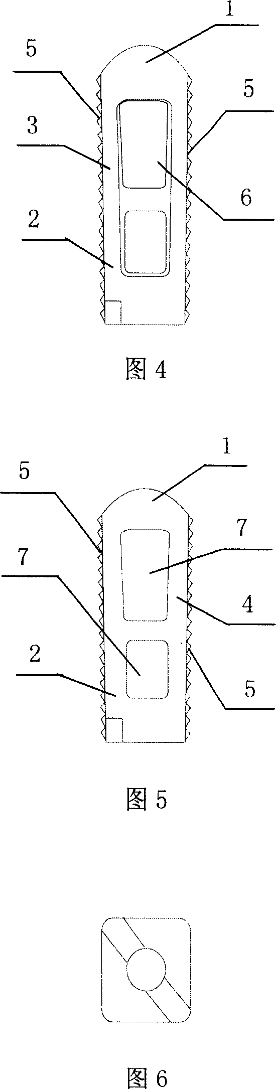
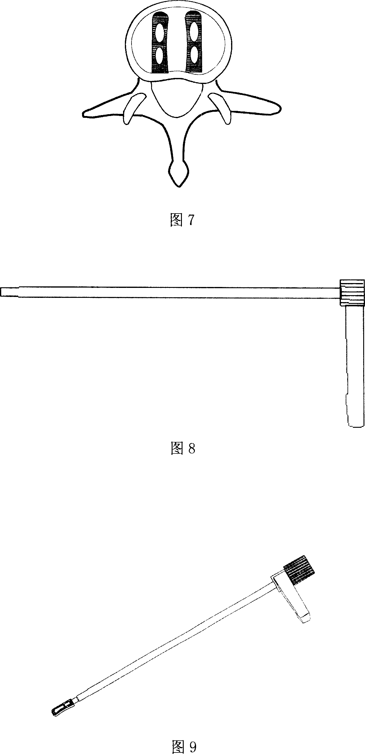
[0039] Please refer to Fig. 1 to Fig. 7, the minimally invasive intervertebral fusion cage, the surfaces between the fusion cage head 1 and the fusion cage tail 2 are two oppositely arranged endplate contact surfaces 5 and oppositely arranged inner insertion surfaces 3 and outer The insertion surface 4 is provided with an opening 6 on the inner insertion surface 3, and the opening 6 leads directly to the interior of the fusion vessel to form an accommodating space inside the fusion vessel; the upper end of the opening 6 is close to the fusion vessel head 1 and the lower end is close to the fusion vessel tail 2. Two openings 7 are provided on the outer insertion surface 4, and the two openings 7 are arranged longitudinally along the fusion device head 1 and the fusion device tail 2 and communicate with the accommodation space; the fusion device head 1 is convex It is arc-shaped and gradually narrows from back to front; the fusion head 1 forms a bullet shape; the transition betwe...


PUM


Abstract

The invention discloses a micro-injury intervertebral fusing tool and using method, which is characterized by the following: the surface between fusing tool head and rear possesses two end-plate contact faces, internal plug face and external plug face; the head of fusing tool is outward arc to minimize from back to front, which transmits between internal and external plug sides. The using method comprises the following steps: (a) plugging internal and external plug sides into intervertebral along level direction; (b) rotating fusing tool by 90 deg along axle to erect the fusing tool; contacting end-plate contact surface and vertebra end-plate tightly; realizing micro-injury operation effectively.

Description

technical field [0001] The invention relates to a medical device, in particular to a minimally invasive intervertebral fusion device and a use method thereof. Background technique [0002] Spinal instability is a common degenerative disease of the spine and one of the common causes of low back and leg pain. For spinal instability, the usual treatment is intervertebral fusion surgery. That is, the decompression of the lamina is completed first, the nucleus pulposus of the intervertebral disc is removed, and the end plate is processed. According to the height of the intervertebral space measured on the preoperative X-ray and the measurement results, an intervertebral fusion cage of an appropriate size is selected and implanted in the intervertebral space. When using the intervertebral fusion device to perform intervertebral fusion surgery, the intervertebral fusion device mainly undertakes two functions: one is to support the intervertebral space with a rigid structure and ma...

Claims


Application Information

Patent Timeline
IPC IPC(8): A61F2/44A61B17/70
CPCA61F2/44A61F2002/30001
Inventor 王建华
Owner 王建华
Why Eureka
Try Eureka