Eureka AIR delivers breakthrough ideas for toughest innovation challenges, trusted by R&D personnel around the world.

Suction chamber for a manifold for water jet treatment of fabrics

A suction chamber and textile technology, applied in the field of suction chambers, can solve the problems that the spray water cannot be sucked away, and the spray water is not sufficiently removed, and achieves the effect of strong air circulation

Inactive Publication Date: 2011-05-11
FLEISSNER GMBH & CO KG
View PDF4 Cites 0 Cited by
  • Summary
  • Abstract
  • Description
  • Claims
  • Application Information

AI Technical Summary

Problems solved by technology

With this device, the corresponding spray water can only be removed insufficiently
In addition, spray water formed on the opposite side of the water jet cannot be sucked away

Method used


Image

  • Suction chamber for a manifold for water jet treatment of fabrics
  • Suction chamber for a manifold for water jet treatment of fabrics
  • Suction chamber for a manifold for water jet treatment of fabrics

Examples


Embodiment Construction

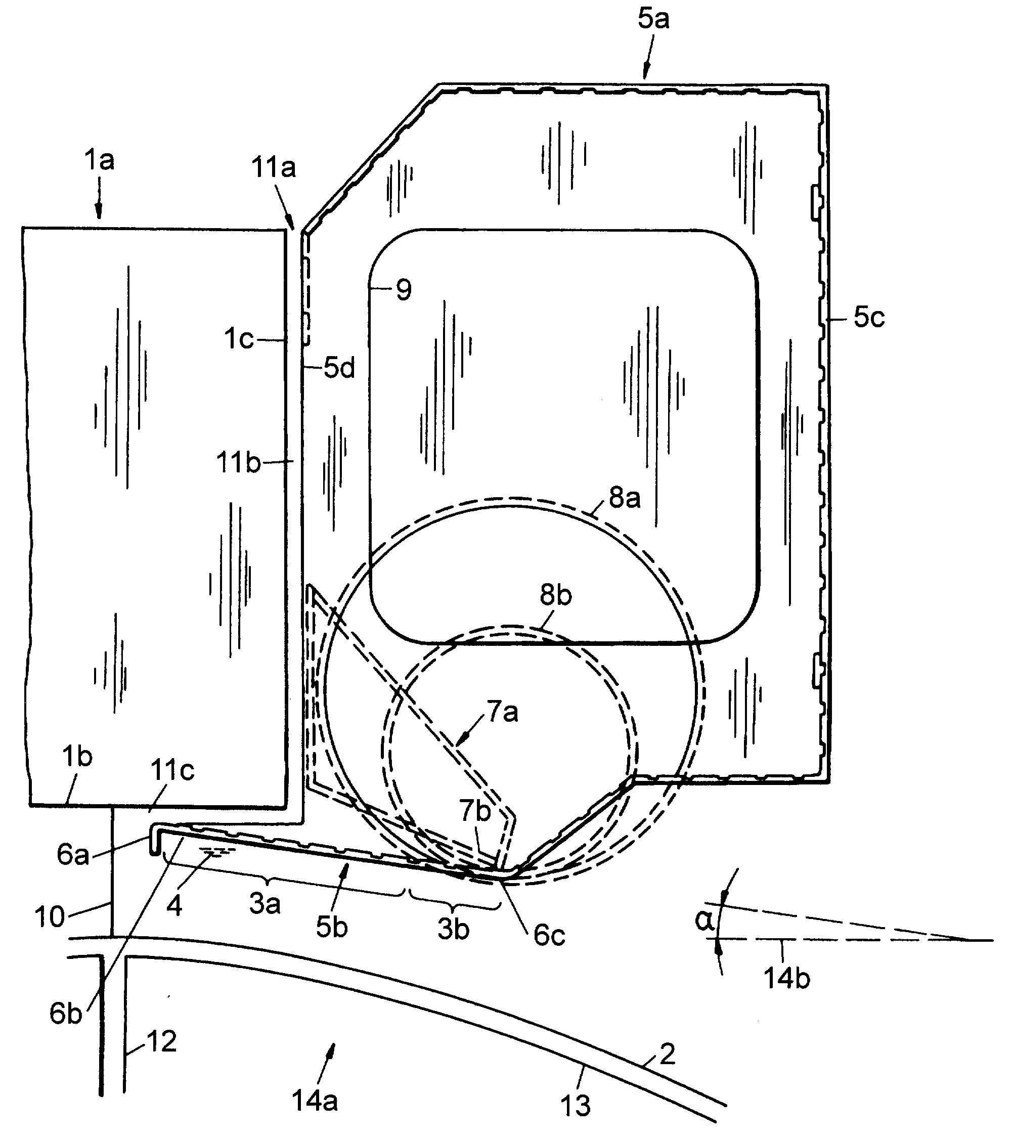
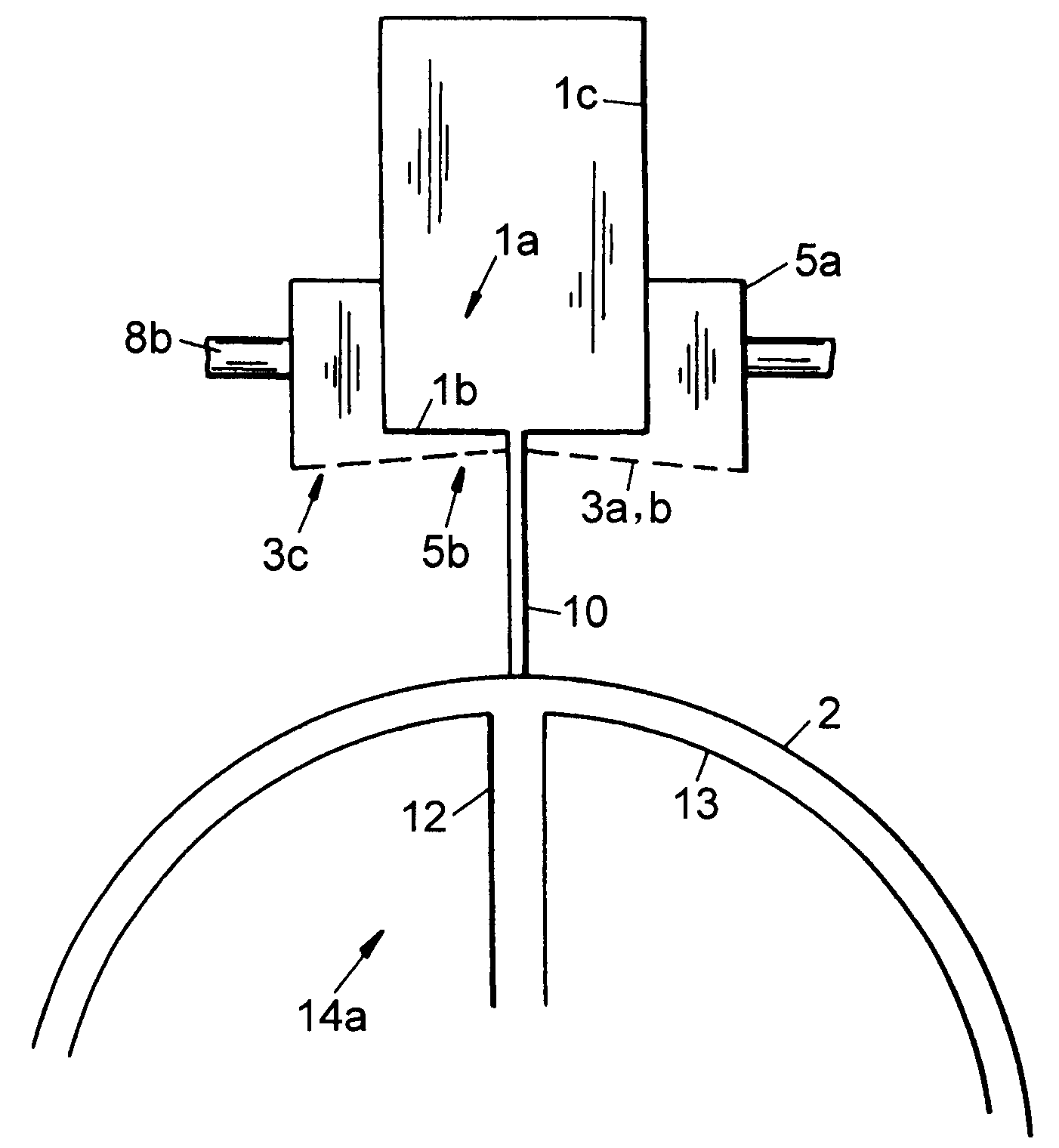
[0032] exist figure 1 , the water beam, denoted 1a, from which a water jet 10 emerges through nozzle openings (not shown in the schematic diagram) and strikes the fabric carrier 13 conveyed through the screen drum or screen drum 14a Textile, mesh or non-woven 2. At the same time, most of the water is led out through the drainage device 12 of the screen drum 14a.

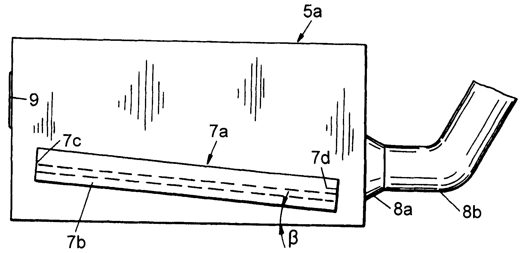
[0033] In the region of the water beam 1a is a suction device or suction chamber 5a which has, on its underside 5b, inclined porous suction surfaces 3a,b with openings 3c so that the water The spray water formed when the jet 10 occurs on the textile, mesh or non-woven fabric 2 is guided to the lower side 5b of the suction chamber and can then be sucked off sufficiently by the suction chamber 5a. Therefore, it is possible to avoid water droplets appearing on the underside of the water beam 1 a and no longer drip onto the woven fabric, mesh fabric or non-woven fabric 2 .

[0034]In this embodiment, the suction chamb...


PUM


Abstract

The invention relates to a suction chamber (5a) for a water beam (1a) for jet impacting on knitted fabric, webs or non-woven fabrics (2) composed of staple fibers, endless filaments or cellulose fibers, either composed of a plurality of layers or mixture thereof. Furthermore the invention also relates to a porous suction surfaces (3a, 3b) used for sucking jetted water (4) and disposed on a lower side (5b) of the suction chamber (5a). The invention achieves the purpose that a water jet released from the water beam is not affected by the jetted water and water fog formed by the jetting in all of the longitudinal direction and / or the latitudinal direction of the water beam in the water jet travel direction, and the conventional general production of water drop under the water beam is prevented. The purpose is realized by such that the suction surfaces (3a, 3b) are disposed in an obliquely extended form, and extended from an upper region (6b) close to the water beam (1a) and / or a liquid-dripping corner (6a) to a lower region (6c) of the suction chamber (5a).

Description

technical field [0001] The invention relates to a suction chamber for a water beam for applying jets to textiles, meshes or nonwovens, which are composed of fiber bundles, continuous fibers or fibers It consists of cellulose fibers, which also consist of a plurality of layers or mixtures, and a porous suction surface, which is arranged on the underside of the suction chamber, is used for suction of flushing water. Background technique [0002] In DE 19923591 A1 a device for receiving liquid sprayed under a water beam has been disclosed. Here, the device is arranged on the side of the water beam over its entire length. A funnel-shaped groove was formed on the edge of the water beam, and a suction groove with a height of about 2 mm was formed on the inner end of the groove. If a sufficiently large low pressure is connected to the additionally closed device, all water droplets, including spray mist, can be sucked away from the underside of the water beam without causing damag...

Claims


Application Information

Patent Timeline
Patent Type & Authority Patents(China)
IPC IPC(8): D06B1/00D06B1/02B05B15/04D04H18/04
CPCD06C29/00D04H18/04
Inventor 乌尔里希·明斯特曼
Owner FLEISSNER GMBH & CO KG
Why Eureka
Eureka Blog
Learn More