
Energy-saving ultra low emission dual-mode homogeneous compression-ignition engine based on fully variable valve mechanism

A valve mechanism and homogeneous compression ignition technology, which is applied to combustion engines, machines/engines, internal combustion piston engines, etc., can solve the problems of reduced mechanical efficiency, failure to meet the requirements of vehicle engines, and low fuel utilization

Active Publication Date: 2013-05-15
TIANJIN UNIV
View PDF0 Cites 0 Cited by
  • Summary
  • Abstract
  • Description
  • Claims
  • Application Information

AI Technical Summary

Problems solved by technology

Due to the limitations of the characteristics of the gasoline fuel itself and many factors such as knocking, the gasoline engine can only use a lower compression ratio, which makes the thermal efficiency much lower than that of the diesel engine, and produces a large amount of NOx and incomplete combustion products. In addition, the gasoline engine needs to use the throttle Control the intake air volume, and the pumping loss at part load reduces the mechanical efficiency. The fuel utilization rate of gasoline engines is 30% lower than that of diesel engines, which is the limit of fuel utilization rate that traditional gasoline engines are difficult to overcome. In order to break through this limit, relevant experts at home and abroad Has been committed to exploring a new generation of combustion process for organizing fuel efficient and clean combustion and developing a new generation of internal combustion engine combustion theory
So far, although the homogeneous compression ignition of gasoline engines has been realized, its operating range is narrow, which is far from meeting the requirements of vehicle engines for various operating ranges.
In 2001, the U.S. Department of Energy pointed out that there are still 9 major difficulties in the HCCI combustion mode, which clearly pointed out that the narrow range of operating conditions and the switching between the two combustion modes have yet to be resolved

Method used


Image

  • Energy-saving ultra low emission dual-mode homogeneous compression-ignition engine based on fully variable valve mechanism
  • Energy-saving ultra low emission dual-mode homogeneous compression-ignition engine based on fully variable valve mechanism
  • Energy-saving ultra low emission dual-mode homogeneous compression-ignition engine based on fully variable valve mechanism

Examples


Embodiment Construction

[0020] engine structure

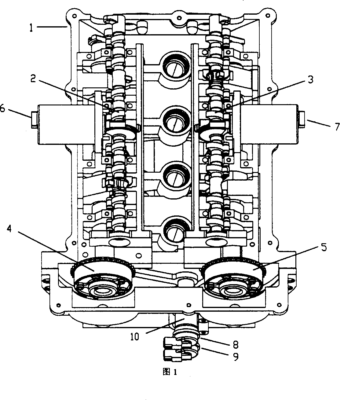
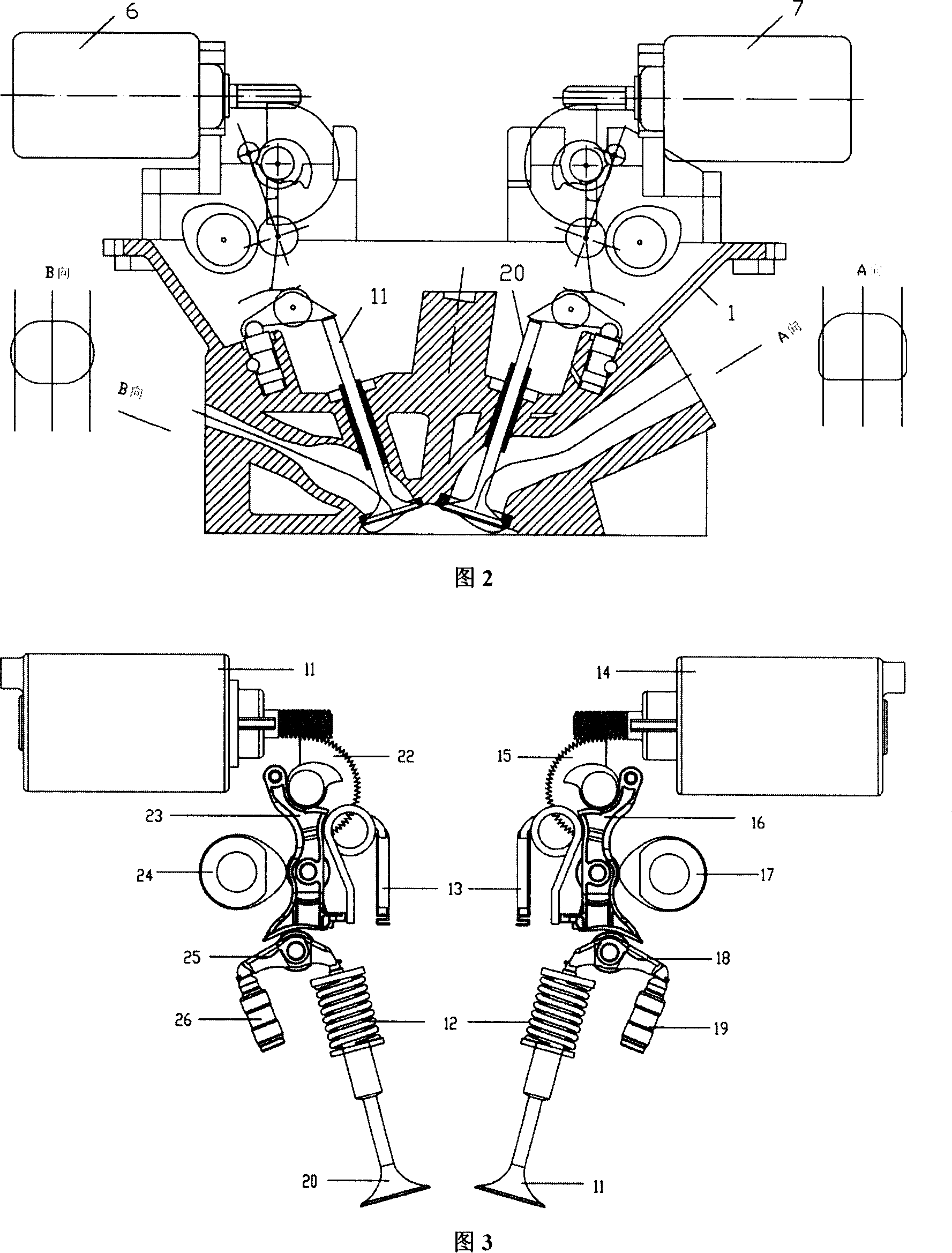
[0021] On the basis of the ordinary intake port injection spark ignition gasoline engine, the fully variable valve cylinder head 1 is adopted, and two sets of valve lift continuously variable mechanisms 2 and 3 are arranged on it, as well as two sets of valve timing continuously variable phase systems 4 and 5, such as figure 1 shown. The valve mechanism electronic control unit receives the intake and exhaust valve lift and phase instructions from the engine electronic management unit, and adopts a closed-loop control strategy to control the servo motors 6 and 7 and the high-speed solenoid valves 8 and 9 respectively to achieve a given intake valve. lift, exhaust valve lift, intake valve phasing and exhaust valve phasing.

[0022] The variable valve lift mechanism is mainly composed of a servo motor, an eccentric shaft and an intermediate swing rod. Its structure is as follows: image 3 shown. The movement of the middle swing rod is jointly control...


PUM


Abstract

The invention discloses an energy-saving ultra-low discharge dual-mode uniform engine, based on variable-throttle device, wherein a cylinder cover is a variable-throttle cylinder cover arranged with two throttle strike continuous changers and a variable-throttle phase device whose frame is arranged with a chain tooth around and connected with a crank of the engine via chain. The inventive engine can completely utilize the high-effect energy-saving ultra-low discharge character of uniform HCCI burning mode to switch between spark burning SI and HCCI burning mode according to working conditions, to save energy and ultra-low discharge. And the variable-throttle device can realize the control on different burning modes, and switch between two modes.

Description

Technical field: [0001] The invention belongs to internal combustion engines, in particular to an energy-saving ultra-low emission dual-mode homogeneous compression ignition engine based on a fully variable valve mechanism. Background technique: [0002] At present, the widely used gasoline engines are based on the spark ignition combustion mode. A large number of basic research results have proved that although various technical improvements have been made to the traditional spark ignition internal combustion engine (gasoline engine), it has been improving fuel utilization. The efficiency and the reduction of harmful emissions have reached the limit, and further development requires a breakthrough in the combustion theory of internal combustion engines. In particular, most of the engines currently produced at home and abroad will sacrifice fuel utilization to varying degrees in order to meet the increasingly stringent emission regulations, so as to reduce the emission of ha...

Claims


Application Information

Patent Timeline
Patent Type & Authority Patents(China)
IPC IPC(8): F02D43/00F02D13/02F02B11/00
CPCY02T10/18Y02T10/12Y02T10/128
Inventor 谢辉胡顺堂张岩何邦全赵华
Owner TIANJIN UNIV
Learn More