Control method for high-power active filter

A source filter and control method technology, applied in active power filtering, harmonic reduction devices, and AC networks to reduce harmonics/ripples, etc. Avoid overshoot and improve system filtering performance

Inactive Publication Date: 2007-08-15
HUNAN UNIV
View PDF0 Cites 14 Cited by
  • Summary
  • Abstract
  • Description
  • Claims
  • Application Information

AI Technical Summary

Problems solved by technology

[0010] In order to solve the technical problem that the DC side voltage of the existing hybrid active power filter fluctuates easily and seriously affects the filtering performance of the filter, the present invention provides a composite control method for the hybrid active power filter

Method used


Image

  • Control method for high-power active filter
  • Control method for high-power active filter
  • Control method for high-power active filter

Examples


Embodiment Construction

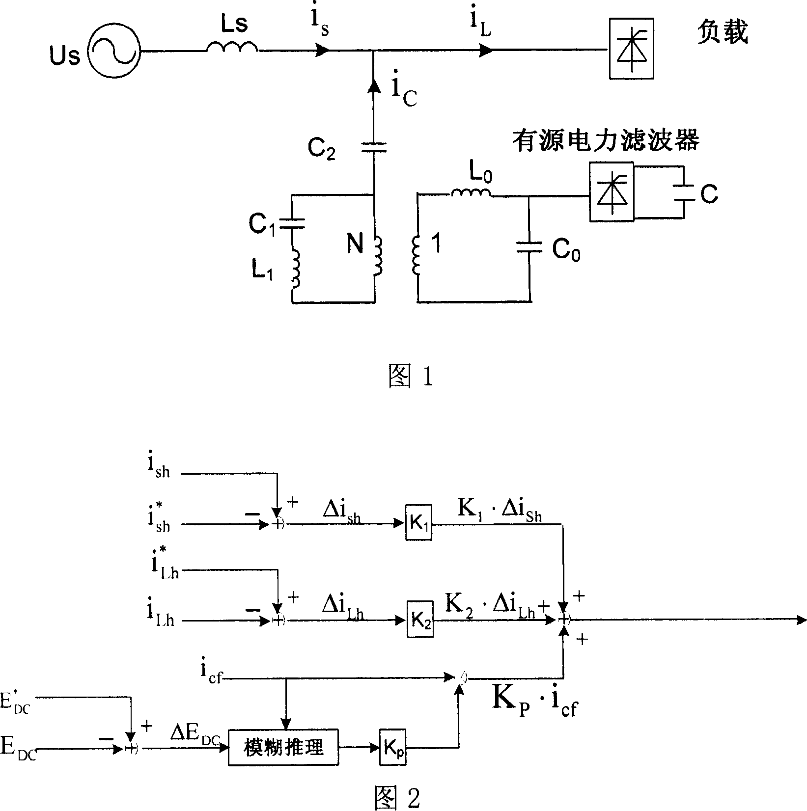
[0024] The structure of the hybrid active filter is shown in Figure 1. It is mainly composed of an active part, an output filter, a coupling transformer, a fundamental series resonant circuit and a passive part. The active part is a voltage-type inverter composed of intelligent power modules. A large capacitor C is connected to the DC terminal of the inverter, and an output filter L is connected to the AC terminal. 0 、C 0 In order to filter out the high-frequency burrs generated by switching devices on and off, the fundamental series resonant circuit is composed of L 1 and C 1 Composition, while L 1 、C 1 and C 2 It also plays the role of a single-tuned filter. The coupling transformer realizes the electrical isolation of the active part and the passive part, and can select the appropriate transformation ratio according to the voltage and current level of the active and passive parts. The passive part consists of LC passive filter banks.

[0025] The composite control met...


PUM


Abstract

The disclosed control method for large-power active filter comprises: detecting harmonic current on power-network / load side and calculating the compensation for harmonic current; detecting the fundamental current and dc side voltage of filter branch to obtain the dc side capacitance voltage control usage; synthesizing all compensation to obtain the control signal for the inverter of an active filter. This invention avoids voltage overshoot, and improves system filter and robustness.

Description

technical field [0001] The invention relates to a control method of a high-power active filter. Background technique [0002] With the increasing number of nonlinear loads in the power grid, the harmonic content in the power grid rises sharply, resulting in serious distortion of the supply voltage waveform, which seriously affects the safe and economical operation of the power grid and electrical equipment, and endangers the normal power consumption of the majority of users. And production. The main method to solve the harmonic pollution of the power grid is to install harmonic suppression devices. Harmonic suppression devices mainly include passive power filters or active power filters. [0003] The installation of passive power filters in the power grid has always been the main means of traditional harmonic compensation. Its outstanding advantages are simple structure, high operational reliability, and low operating costs. However, the filtering performance of the passi...

Claims


Application Information

Patent Timeline
Patent Type & Authority Applications(China)
IPC IPC(8): H02J3/01
CPCY02E40/40Y02E40/22Y02E40/20
Inventor 罗安赵伟帅智康范瑞祥孙贤大舒适
Owner HUNAN UNIV
Why Eureka
Try Eureka